A related question is a question created from another question. When the related question is created, it will be automatically linked to the original question.
If you have a related question, please click the "Ask a related question" button in the top right corner. The newly created question will be automatically linked to this question.
1. May I know Frequency-Jitter tolerance about UCC28700? example fs equal 60kHz. 2. May I know Duty Ton control method about UCC28700? Depend on what condition?
The frequency-jitter function of the UCC28700 operates as follows:
A nominal switching frequency (Fsw) is targeted at maximum power (in your example, it is 60kHz).
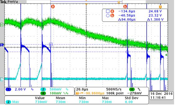
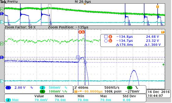
The DRV output consists of 4 cycles at (Fsw + 7.5kHz), followed by 4 cycles at Fsw, followed by 4 cycles at (Fsw – 7.5kHz), then repeats. This is a sawtooth pattern, not a triangular pattern. At the higher frequency cycles, the transformer peak current is reduced by -3.5% from nominal, and at the lower frequency cycles, the peak current is increased by +3.5%, to keep the average energy delivered per cycle relatively constant during the jittering.
The Ton duty cycle is controlled by the level of an internal error voltage (Vcl), which cannot be viewed externally. However, Vcl is proportional to the average load power. The Control Law curves of Figure 15 in the UCC28700 datasheet (page 14) show that the primary peak current (Ipp) varies when 2.2V < Vcl < 3.55V. This is the Amplitude Modulation (AM) region, where Ton varies to modulate Ipp. Above 3.55V and below 2.2V, Ton is fixed and power throughput is controlled by FM. Maximum Ton and Ipp(max) are determined by the design procedure for this device, found in section 9.2.2 on page 18.
In actuality, it is the current-sense threshold voltage (Vcst) at the CS input that is controlled by Vcl in the AM region, and Vcst in turn determines Ipp, which results in a particular Ton, depending on the output power level. In the UCC28700, Vcst ranges from 750mV maximum to 250mV minimum.
If this answers your questions, please click on the “Verify Answer” button.
The internal timing control of the UCC28700 gate is proprietary information, but it follows the scheme which I described in my previous reply. The switching frequency and gate on time are set according to the Vcl voltage in the Control Law (Figure 15, page 14 of the datasheet). The nominal switching frequency is set by the Vcl. The gate-drive is turned on long enough for primary peak current Ipp to reach the level determined by Vcl, then is turned off. The level of Ipp is sensed at the CS input. The error voltage Vcl is a function of the output power level. Higher load results in higher Vcl, high frequency and high Ipp. Low load results in low Vcl, low frequency and low Ipp.
This file illustrates the EMI jittering scheme implemented in the UCC28700 device family. EMI Jitter - UCC28700.pdf The actual cycle-by-cycle jittering is modified by additional disturbances such as valley switching, load perturbations and noise, so the observed jitter may deviate considerably from the ideal pattern described.
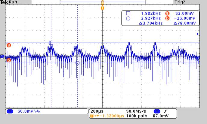
Hi Kuo, it looks like some noise is being injected onto the Aux winding which is causing an increase in the winding voltage at the instant that it is sampled to determine the output voltage. This makes the output voltage look too high to the controller and it therefore decreases the switching frequency and peak current.
Is the flyback operating in a system with other switching stages? Is there something else which could be injecting noise into the aux signal?