This thread has been locked.

If you have a related question, please click the "Ask a related question" button in the top right corner. The newly created question will be automatically linked to this question.

IOUT_OC_FAULT_LIMIT erroneously triggered on TPS40422

Other Parts Discussed in Thread: TPS40422

Hi, 

I'm operating the device, TPS40422,  in 2-phase mode, and having it generate up to 18A at 0.95V. The Fusion Digital Power Designer GUI shows it stops working when the load reaches about 17A (roughly 8.5A for each output) in that over-current condition is triggered. The IOUT_OC_WARN_LIMIT and IOUT_OC_FAULT_LIMIT, however, are set at 27A and 30A, respectively, for both outputs. The temperature monitor shows only about 35 degree C. Why did it happen? 

Thanks

Nikko

  • Hello,

    Is there anybody who can help me with the issue or ran into it before?

    Thanks
    Nikko
  • Let me see if i can find someone to assist you.

  • Hi Nikko,

    18A is total current or phase current?

    IOUT_CAL_GAIN should be equal to inductor DCR value to make the current readout and OC accurate.

    Can you check if IOUT_CAL_GAIN is set correctly?

    Thanks

    Qian

  • Hi Qian,

    18A is the total current. IOUT_CAL_GAIN is set to be 6.719mohm which is the closest to the inductor's DCR (6.7mohm). After setting the value I also did a kind of calibration, i.e. adding a known load of 1A to the rail and saw each phase's current going up by about 0.5A.

    Thanks
    Nikko
  • Hi Nikko,

    IOUT_OC_FAULT_LIMIT is to set OC threshold PER PHASE in 2phase configuation.
    If IOUT_OC_FAULT_LIMIT is set 30A in your test, the OC threshold of total current should be 2*(30A-0.5*Iripple), because OC circuit is detecting the inductor peak current. Your test result 18A is much lower than the calculation value.

    Is current readout accurate before OC happens?
    Can you send your schematic in pdf file and Fusion project file (.xml file) to below address:
    Q-CHEN@TI.COM

    Thanks
    Qian
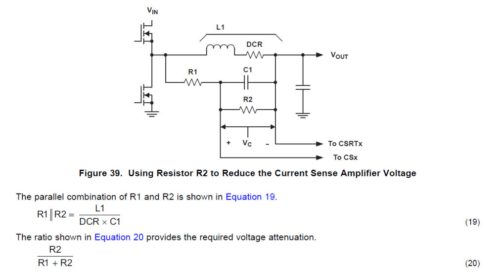
  • It happens because the voltage across CSxP and CSxN exceeds 60mV which is the maximum threshold. The instantaneous voltage equals DCR*inductor current. Here DCR=6.7 mohm, when the phase current is about 9A it leads to 9A*6.7mohm=60.3mV. According to the datasheet, " If the voltage across these pins exceeds this maximum threshold, the overcurrent fault or warning will be tripped, regardless of the setting of IOUT_OC_FAULT_LIMIT and IOUT_OC_WARN_LIMIT." To fix the problem, a resistor should be added in parallel with the capacitor of the low-pass filter. At the same time the attenuation factor of R1/(R1+R2) should be added to  IOUT_CAL_GAIN so that the current reading is correct.