This thread has been locked.

If you have a related question, please click the "Ask a related question" button in the top right corner. The newly created question will be automatically linked to this question.

LM5050-1: As an OR-ing Diode for Batteries

Part Number: LM5050-1

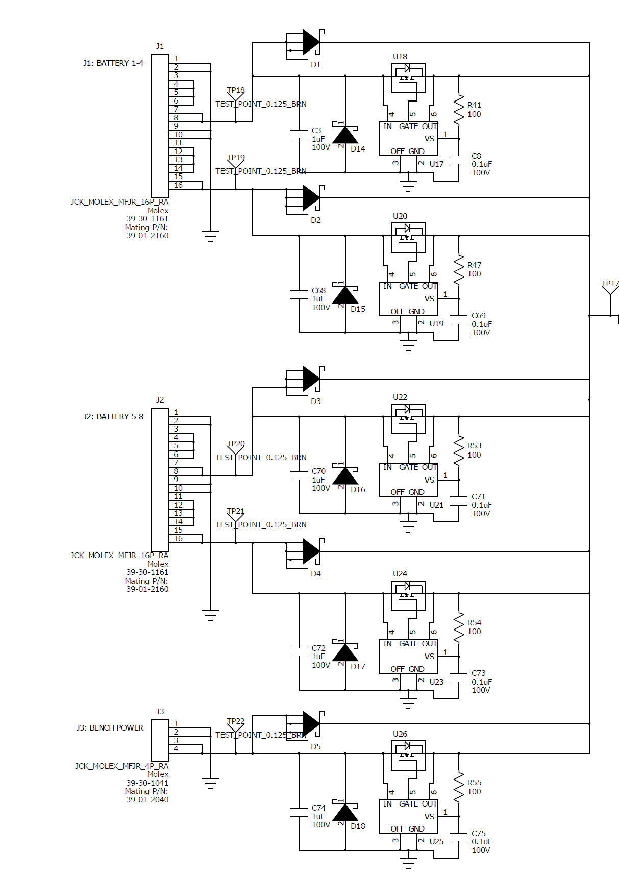
I am designing for an application with four parallel 48V nominal battery banks. I am trying not to use Schottky diodes because even they are using too much power. I would like to use the 5050-1 but there is one line in the data sheet that is worrying me:

8.1.1 MOSFET Selection 4. (b)
Reverse current leakage. In cases where multiple input supplies are closely matched it may be possible
for some small current to flow continuously through the MOSFET drain to source (that is, reverse)
without activating the LM5050-1 Reverse Comparator. Higher RDS(ON) will reduce this reverse currentlevel.

As the power supplies are batteries, there will be times before they even out that they will be very close to each other. Can you comment on how much a "small current flow" is and if this would be detrimental to the LM5050 or FET?

  • Hi Ben,

    First off, Welcome to E2E. Secondly, thank you for considering our device. The LM5050-1 is a linear regulating OR-ing controller. What that means is the device will regulate the voltage drop across the source and drain of the FET to around 22mV (typical). If the FET chosen has a very low Rdson, and a small amount of current is flowing through the FET, then the gate voltage decreases which increases the Rdson of the FET. The gate voltage will decrease until there's a 22mV difference across the source to drain. If the Vsd is greater than 22mV, then the gate voltage increases up to a max of Vin + 12V.

    If two or more batteries are roughly the same voltage, and there's a small amount of current flowing through one of the LM5050 devices, the gate voltage will decrease until there's a 22mV difference across Vsd. At this point, the Rdson has increased. If there's a small amount of current flow in the reverse direction, then the gate voltage will decrease, which will increase the Rdson, which will activate the reverse current trip threshold (-28mV typical) and shut off the gate extremely fast (around 60ns for a Cgate = 10nF, and 180ns for a Cgate = 47nF). I wouldn't be concerned Ben. This device is used in many parallel power supply applications (both battery and wall powered supplies).

    I hope this helps :-)

    Best Regards,

    Aramis P. Alvarez

  • Hi Aramis,

    Thank you very much for your reply. I went ahead and used the chip. Just to be safe I included D1-D5 which are standard schottky diodes in case the smart diode's did not work (but I have not populated them).  I added the filter on VS to be safe and the recommended input transient protection. See attached schematic image. J1 and J2 are the battery inputs, 24V gets applied on pins 1-4 and then is put in series with another 24V on pins 5-8. This is repeated for pins 9-12 and 13-16. So there are four 48V inputs between J1 and J2. There is also J3 where 48V can be applied from a bench power supply.

    At first I just used the bench input and it worked fine, but later, possibly related to lowering the supply to ~30V and then back to 48 the U25 pin 5 (gate line) blew off the board. It destroyed the trace, so when replaced the circuit does not work anymore. I then put battery power on J1 and U19 did the same thing. after removing and reapplying the batteries again, U21 blew, and there wasn't even batteries hooked up to J2. Not sure what I have done wrong.....

    If it looks like there is nothing wrong I guess I'll go with the Schottky diodes because I am running out of time to make the smart diodes work. But I really would like to save the power. 

    Thanks!

  • Hi Brand,

    Sorry to hear that. I have several observations/comments:

    1) I noticed that there isn't a Cout connected to any of the outputs. Do you have one populated? If not, then a 22uF-47uF should do the trick. 

    2) What type of load are you driving (resistive, current), and what is the value of that load?

    3) How much current are you measuring from the power supply? 

    4) What type of FET are you using, as in model number? Make sure that the FET can withstand the power being applied here. The FET's SOA curve on the datasheet will give you this type of info. 

    Best Regards,

    Aramis P. Alvarez