This thread has been locked.

If you have a related question, please click the "Ask a related question" button in the top right corner. The newly created question will be automatically linked to this question.

LM3434SQ-20AEV: PWM connections for the LED driver

Part Number: LM3434SQ-20AEV

Hi,

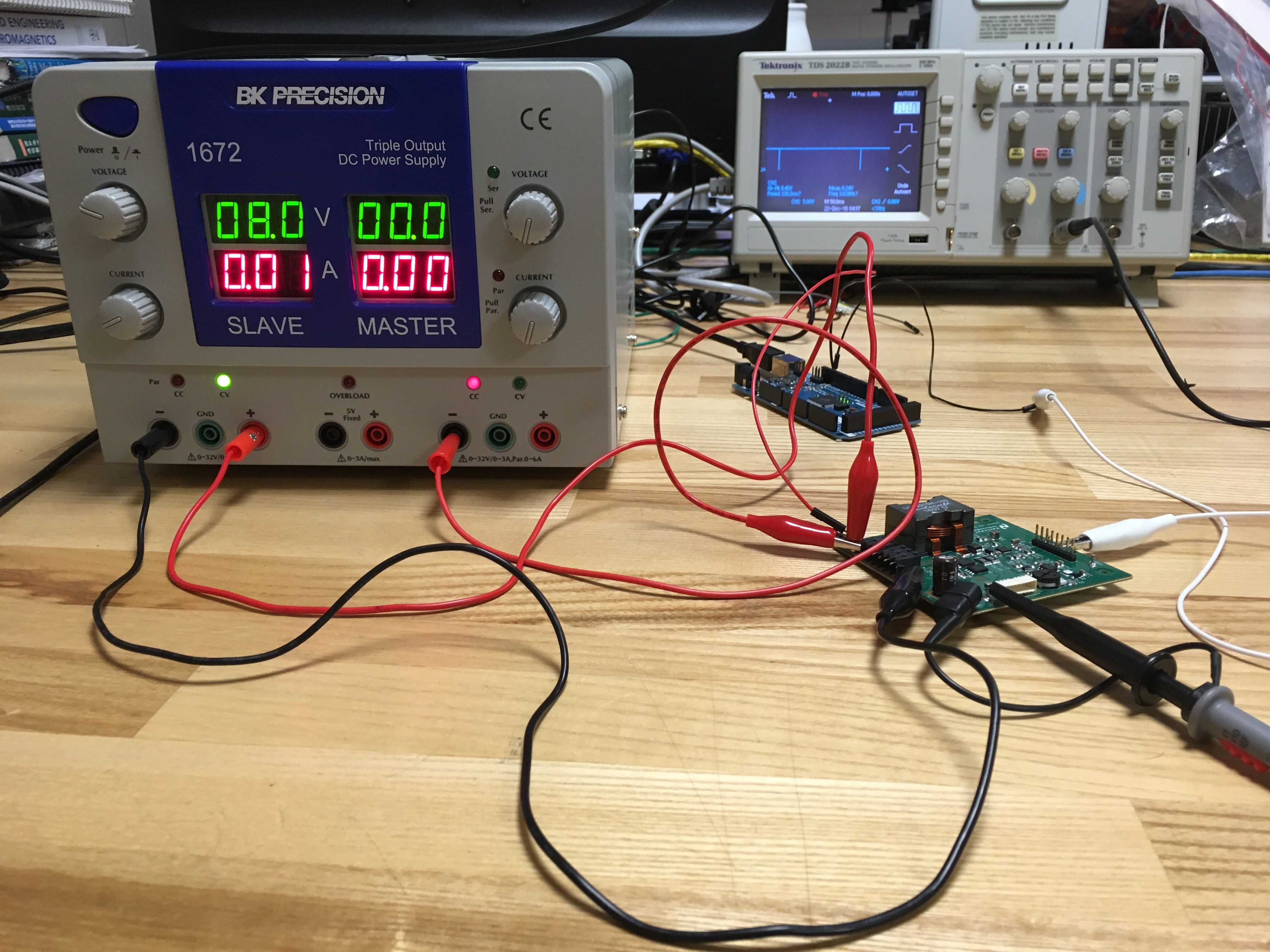
I am trying to give a PWM signal from an Arduino MEGA 2560 board to the LM3434 LED driver. I can only see a PWM pin on the LED driver board and want to know where to connect the PWM signal ground and the power supply ground.

With the connections below ( that is negative of the power supply to -12V on the LED driver board, positive of the power supply to GND on the LED driver board, Signal output from the Arduino to the PWM on the LED driver board, Signal ground from the Arduino to the GND on the board and Osciloscope probes to the LED + and LED - pins ), we are getting an inverted pulse on the oscilloscope as can be seen in the second picture.

Can you please tell me how I can get a positive pulse? Is there something wrong in my connections? Thanks.

  • Hello Aparna,

    The LM3434 was designed as a dual supply device for common anode to ground configurations. It can be used with a single supply and the EVM was designed that way using the LM5002 to generate the second supply for biasing VIN and the control circuitry above the CGND pin. So signals fed to DIM, ADJ, and EN all need to have their grounds referenced to the CGND pin which are the connections labeled "GND" on the EVM. They can't be referenced to the "-12V" connections that the ground of your supply is connected to.

    Best regards,

    Clint

  • So, we need not connect the positive terminal of the power supply to GND on the board? When we connect just the negative terminal to -12V on the board and the chassis ground of the power supply to GND of the board, the multimeter shows us 0V. When we connect he negative terminal to -12V on the board and the positive terminal of the power supply to GND of the board, the multimeter shows us the correct negative voltage. But in this case, we are unsure of the ground connections for PWM signal. We have connected it to GND as well. Can you please clarify what connections we need to make?

    Thanks and regards,

    Aparna

  • Hello Aparna,

    The EVM was designed for ease of use with a single main power supply. But if you want to directly drive any of the control pins I mentioned you will need a second isolated supply for the control circuitry. Your main power supply that supplies the majority of current is still connected with its negative terminal at "-12V" and the positive terminal connected to "GND". But use another power supply that does not have a ground common to the first to power your MCU board. That board and PWM signal needs to have their grounds references to the "GND" of the EVM.

    Regards,

    Clint

  • Hello Clint,

    MCU board is powered by the laptop USB port. So the ground is not common to the first power supply. Should we connect it to an external power supply instead?

    Regards,
    Aparna
  • Hello Aparna,

    So you connected the MCU board ground to "GND" and the PWM output to "PWM" and you are still not getting a square wave signal at the PWM pin? If you are is it high enough to cross the 1.6V threshold? If you are not you may want to try a separate supply. I don't know how a USB power source is grounded, but if it uses earth ground and the supply does as well it may cause issues.

    Regards,

    Clint