This thread has been locked.

If you have a related question, please click the "Ask a related question" button in the top right corner. The newly created question will be automatically linked to this question.

TPS65400: TPS65400 Input Capacitor

Part Number: TPS65400

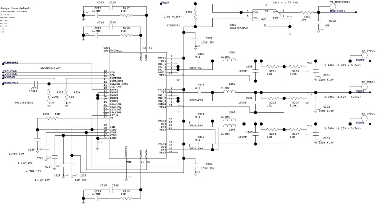
Hi, I cannot find any documentation on the input capacitor requirement for the TPS65400.  My outputs are +4V at 1, 2, and 34  When I designed my board, I use one 10uF at the PVIN12 side and one 10uF at the PVIN34 side.  What I found is that if the input voltage goes very low below about 7V and with high 3-4A current on all outputs, there will be oscillation of about 5kHz at the input terminal.  This looks like sub-harmonic oscillation.  It seems like it cannot be cure by any changes in the compensation RC network, changes in the slope compensation programming, or output phase change programming.  The only way I can cure the oscillation is by adding a very large 100uF input decoupling capacitor on both side.  Then I went back to the EVM which uses 22uF on both side and tried the same test.  I found that the EVM also exhibit a small amount of instability at the same condition, although it does not go directly into the oscillation mode.  I wish TI can provide better documentation and application regarding the input capacitor requirement.

  • Hi Henry.

    1, What's your 10uf rated voltage and How about your 10uf DC bias curve, if it is not good, when input voltage added into the mlcc, the 10uf cap value maybe have a large derating. so that there is no enough power to provide when converter switching.

    2, Draft estimate capacitance value Cin=Iin/(deltaVin*fsw)

    3, if you need to get more, please upload your schematic, test waveform and your capacitance datasheet.

    BR,

    yuchang

  • Hi Yuchang,

    My 10uF are rated at 25V, and I am only using it at 12V.  Besides, the oscillation problem increase with lower voltage, so I do not think the voltage derating is the major problem.

    Your equation is for input capacitor requirement is mainly for voltage ripple.  But in my case it is a stability issue.  The fact is that if I turn on each output independently, there is no oscillation.  It only oscillation if there are high loads in at least two channels.

    My capacitance being used is Samsung CL31B106KAHNNNE.  Attached is my schematic.

    Samsung CL31B106KAHNNNE
  • Hi Henry,

    Yes, the 10uf u used is 25V but the DC bias looks not good, alomost over 60% derating. the real value maybe is only <5uf@12V and so more caps is needed.

    and the draft calculation is for deltaV, if deltaV is very big, then which indicates the Vin will goes down a lot.

    Two channels could cause oscillation, because more power need be provided from Vin, so that make sense.

    Finally, I see there is a current sense resistor in the PVin loop, did you try to remove or short it and re-test to check if there is any promoted?

    also remind that make sure the input power has large current limited ability to provide enough current instantly.

    yuchang

  • Hi Henry,

    Add three more advice,

    1, Did you try the same cap as our EVM mounted, if the phenomenon is same?

    2,Did you disconnect R251, U202 and add external 12V power supply to PVIN to double check the oscillation?

    3, BTW,  the PVIN cap should be placed colse to PVIN pin,

    and if convienient, please upload your waveform, both yours and our EVM you tested.

    BR,

    yuchang

  • Hi Yuchang,

    You got it!  Once I connect the power directly to the PVIN pin, the oscillation goes away.  Then I suddenly realized that I had an input LC filter to this circuit before the R251 resistor, and I was supplying power through the LC filter.  The LC is 10uH and 40uF which calculates to a 8kHz resonant frequency, then once it coupled with the negative input resistance of a buck converter, it became a perfect oscillator.  Now even if I connect the power directly to the LC filter output, there is no oscillation.  This means that it is the 10uH input inductor that caused the problem.  But for the design, I have to keep the inductor, so I have to really push down the input filter corner frequency by replacing the 40uF with something much bigger.  Maybe you can point me to some application note to show how to select the proper input filter to avoid this problem.  Again, Thanks a lot for your suggesstion.

    BR, Henry

  • Hi, Yuchang

    thank you very much~

    Hi, Henry

    Only during ON time, IC draw current from Vin supply and Vin cap, during OFF time, Vin supply charge Vin cap, it means the ripple on Vin pin should have same frequency with switching, and 4 channel buck have phase shift during one period, the Vin ripple frequency shoud > switching frequency.

    So if the Vin have 5K ripple, it must not be swiching caused.

    The Vin voltage sub-harmonic oscillation, from your description, it seems not related with our IC, maybe:

    1. it looks like that the Vin trace parasitic inductor & Vin cap have LC oscillation.  

    2. And also maybe the previous power system have stability issue.

    So please double check the Vin power supply trace and stability of previous power system.

    Thanks.

    Zhao

  • Hi, Herry

    :), it really is LC oscillation.

    1. What is the function of inductor?
    2. To avoid this problem, the best way is increasing input capacitor.

    thanks.

    zhao
  • Hi Zhao,

    The inductor is for another input stage of a forward converter.
    So increasing the input capacitor (output capacitor of the LC filter) does help. But it still needs to be a very large. What I wish to get is the quantative capacitance value to get enough margin to avoid the oscillation. As I realized that a buck converter behaved like a negative resistor so I should set the LC filter corner to be much lower than the negative resistor of the buck. Is there a theoretical calculation to give a rough calculation of the frequency response of the input impedance of this buck converter?
  • Hi, Herry

    The buck converter input impedance = -Rload/(D^2). (Rload is the load of buck.)
    so the model can be simplified to LCR circuit.

    Zhao
  • Hi Zhao,

    Your equation of Rload/(D^2) seems to be a DC resistance equation if we assume D does not change.  But the fact is that D will change with Vin.  What I am looking for is a small-signal equation for the impedance of this buck converter.  I think this equation should be affected by the design of the compensation netwrok and by the design of the chip itself.  Once I have this equation, I can figure out how to design the input LC filter to avoid oscillation.

    Henry

  • There is a good reference here: Literature Number: SNVA538 - Input Filter Design for Switching Power Supplies

  • Hi, Herry

    Yes, you are right.

    But we can derivative this equation, and calculate the MAX and MIN impedance.

    we only need to calculate the worst case impedance.

    thanks.

    zhao

  • Yes, you are right. The minimum input impedance is when D is 100%, so 4V/12A = 0.33ohm. According to another paper I found in the internet, the input capacitor must be greater than L / R^2, so with my 10uH input inductor, the capacitor must be at least 100uF.