This thread has been locked.

If you have a related question, please click the "Ask a related question" button in the top right corner. The newly created question will be automatically linked to this question.

BOOST CONVERTER

Guru 13485 points
Other Parts Discussed in Thread: TPS55330, INA139

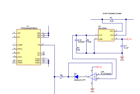
 looking to charge a 560uF capacitor from 5V to 16V. The circuit should support a way to set the current limit and it would be good if the current limit function would act as a constant current source (from the input rail) while charging the cap and then would turn into constant voltage source after the target voltage is reached. The input charging current we would like to get as a target is around 500mA. A The following part from Linear could be used as a reference: http://cds.linear.com/docs/en/datasheet/1618fas.pdf
The potential is high for this design (the solution needs to be price sensitive) 

  • I would recommend that you try Webench design center to select a part:

    www.ti.com/.../overview.page

    You may not need adjustable current limit for charging if you select a device such as TPS55330 that has adjustable slow start time. At start up, the output voltage (capacitor voltage) is ramped up at a constant rate. i = C * dV/dt so for a constant charge rate, the current is constant. In your case,
    dt = C * dV / i = 560E-6 * 16 / 0.5 = 17.92 msec. That is right in the common range for adjustable slow start. Let me know if that will work for you.
  • Hello Jon
    We need to monitor the input current rather than the output current. Since our apploication is USB powered, the maximum allowed current from the USB rail is 0.5A (in our application). In your suggestion below, when the output voltage is 15V, the input current would be ~1.5A which is not allowed. Can you offer a solution with input current limit?
  • Actually, it does monitor the input current, but only during the switch "on" time. For a boost converter, when the switch is on, the input voltage is connected across the inductor to GND, storing energy. This is the current that the current limit "sees", not the output current. Can you tell me more about your application? If it is USB powered, there is a possibility we already have a reference design similar to it.

    Just FYI we are on holiday now in the US, so it may be a while before I can research it (I often answer generic posts that I possibly know the answer to from memory...even on Christmas day).
  • Hello John
    Yes, it’s USB powered. Regarding your comment below, in this case, since the voltage is rising, the capacitor charging current would drop as the output voltage rise, correct?
  • No the current stays constant. You are charging at a fixed dV/dt set be the output voltage and SS time.
  • Something is still not clear. If I charge at constant current, how can the input current stay the same and vice versa. Since this IC merely converts energy from input to output, how do you explain this behavior?
  • Hi,

    One thing to add. The TPS55330 SS does not work like most of our other parts. Instead of the SS pin being an input to the error amplifier, it clamps the output of the error amplifier which is the COMP voltage. This means it does not give a constant dV/dt based on the SS voltage. Also with a boost a constant dV/dt on the output is a constant output current but not a constant input current. As the output voltage increases, more input current is required to keep the same output current because the conversion ratio changes.

    To get constant current from the TPS55330 I would recommend using an INA139 or something similar. An example circuit is below from a reference design. U3A brings the FB pin above the reference when the current is too high.

    Best Regards,
    Anthony