This thread has been locked.

If you have a related question, please click the "Ask a related question" button in the top right corner. The newly created question will be automatically linked to this question.

TPS61202: TPS61202 - High consumption with no load (floating output)

Part Number: TPS61202
Other Parts Discussed in Thread: TPS61200

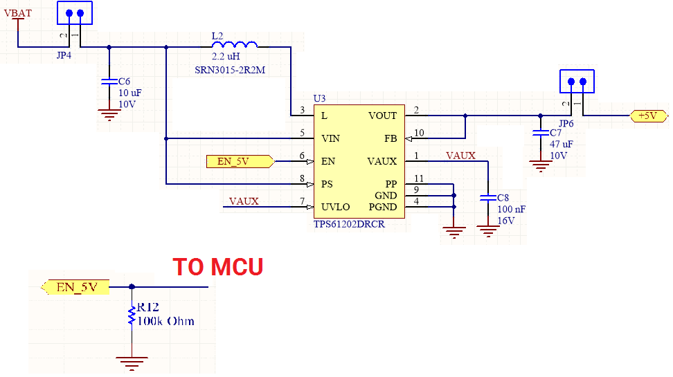
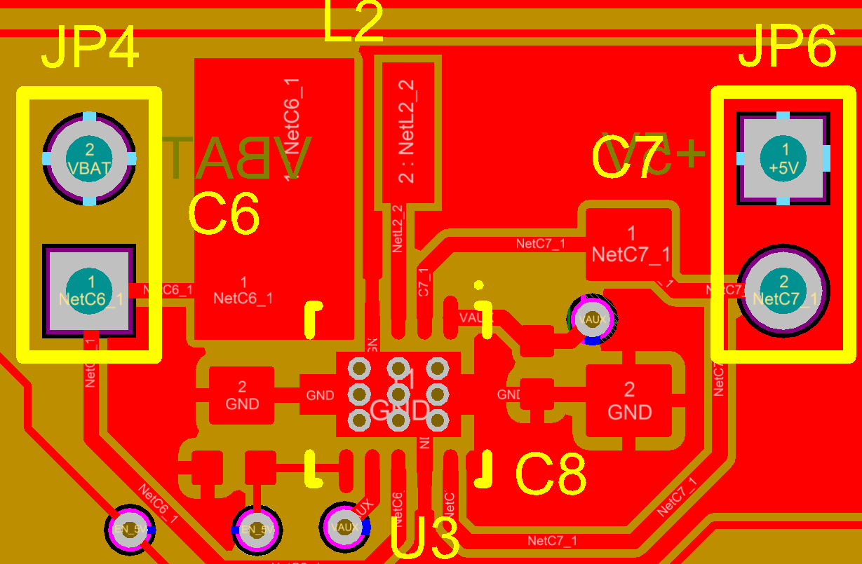
Schematic/layout are below. Tested on multiple boards and platforms (even a modular platform which doesn't have any load connected on the boost output). Problem is high static power consumption (9-10 mA) of boost when enabled and no load attached (power save is disabled: PS connected to input). EN is pulled down (100k) and controlled by a 2.8V powered host. UVLO is disabled (connected to VAUX). Following is the details of the tests and my findings. Any help would be greatly appreciated!

Normal usage:

INPUT: Lithium Polymer battery (3V - 4.2V)

OUTPUT: 5V, max load 700 mA

Test 1)

INPUT: Li-Po battery with Voc = 3.8V

OUTPUT: 5V, no load (floating)

When the host enables the boost, it sinks 9-10 mA of static current (JP4). Expected 70 - 100 uA.

Test 2)

INPUT: Floating

OUTPUT: Lab power supply 5V (max current set at 200 mA)

When the host enables the boost, it sinks 12 uA of static current in the output supply (JP6)

Test 3)

INPUT: Lab power supply 3.8V input (max current set at 200 mA)

OUTPUT: 5V, no load (floating)

When the host enables the boost, it sinks 9-10 mA of static current (JP4).

  • hello
    please enable the power save mode if you requirement small input current at no load condition. if the power save mode is disable, the device keeps switching with approximately 1.4MHz even at no load condition, which consumes large input current.
    could you connect PS pin to GND and measure the input current again?
  • Hello. I just confirmed my measurements with a TPS61202EVM I received. I measure 7.75 mA with power save disabled and 128 uA with it enabled (no load). The enable pin is controlled by our host so we will turn it off when not used, but I will keep that in mind for a future PCB revision.

    Best regards,
    Sebastien
  • One concern with the application is the output current capability. the TPS61200 would trigger current limit at VIN=3V and IOUT=700mA. the maximum output current at VIN=3V is calculated by 3*1.2A*0.85/5V = 0.61A, 1.2A is the minimum avarage input current limitation. this output current is lower than the max IOUT of this application. so the current limit will tigger and VOUT decrease to 4.5V level
  • Ok good to know. Thanks for the info!