Because of the holidays, TI E2E™ design support forum responses will be delayed from Dec. 25 through Jan. 2. Thank you for your patience.

This thread has been locked.

If you have a related question, please click the "Ask a related question" button in the top right corner. The newly created question will be automatically linked to this question.

UCC2895: OUTC and OUTD duties change suddently

Part Number: UCC2895

Hello all,

I am using the Phase-Shift PWM Controller UCC2895 for a DC/DC full bridge converter of 10kW with a fixed frequency of 200 kHz.

I am experiencing some problems with sudden changes of duty in the OUTC and OUTD not related with the comparison of EA and RAMP signals. The problem seems to increase or decrease depending on the working point of the converter (relation between Vin and Vout).

I have verified that the EA signal is completely stable and I have tried to add decoupling capacitors in the EA and the RAMP pins to ground but it did not make any effect. I also tried to change the RAMP shape to see if the problem was related with this signal (increasing R100) but it had no effect neither.

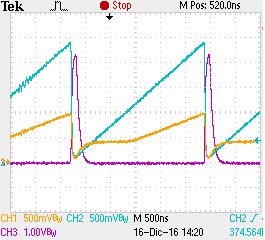
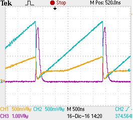
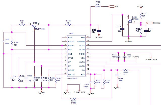
I attach the figures of the OUT signals and the RAMP signal. I also send you the electric scheme to show you the configuration of the IC. I can send you the gerbers too.

OUTA (amarillo), OUTB (azul), OUTC (rojo), OUTD (verde)

RAMP (amarillo), CT (azul), SYNC (rojo)

Configuración UCC2895

Thank you in advance.

Ramon

  • amarillo (yellow), azul (blue), red (rojo) and green (verde)
  • Ramon,

    Thanks for your interest in the UCC2895 device. I have contacted the applications team for this device so we can address your question. Someone should provide assistance within the day.

    - Daniel
  • Ramon,

    It seems like you posted the same oscilloscope image twice. The first image shold show the OUTC and OUTD signals, per your caption, but only three signals are shown, and the waveforms are the same as the second image. Could you please provide the plot with the OUTC/D signals? Thanks.
  • Hi Ramon,

    As Daniel said, could you please provide the plot of OUTC/D together with COMP and CS signals to clarify the issue your met?

    Thanks
    Oliver
  • Hi Oliver and Daniel,

    I send you the figures of the OUTPUT signals and the EA and CS signals. As you said, in the last post I attached the same figure twice.

    OUTA (yellow), OUTB (blue), OUTC (red), OUTD (green)

    EAP (yellow), CS (blue), OUTC (red), OUTD (green)

    In both figures, the OUTC signal has pulses of different lenghts, the OUTC signal pulse in the middle of the figure is longer than the others for example. The OUTC (and OUTD) do big changes of duties from pulse to pulse.

    Ramon

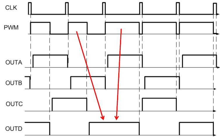
  • The logic of phase shifted control at steady state provides 50% duty cycle pulses at outputs A, B that are synchronized with clock and start PWM cycle. The outputs C, D are determined by internal PWM comparator and complete the PWM cycle using phase shifting versus outputs A, B. At steady state, outputs C, D also operate at 50% duty cycle. If for some reason, PWM duty cycle changes abruptly, this causes outputs C, D change duration next half-switching cycle and operate not at 50%, as it is shown in timing diagram below.

  • Yes, I undersand your approach.

    I am trying to figure out what is the reason of this changes of duty cycle in the OUTC and OUTD.

    The signal EAP is apparently constant and I tried to filter more this signal but I have not detected any improvement.
    The signal CS is filtered and I have connected to GROUND and the problem persists.
  • Yes, I understand your approach.

    I am trying to figure out what is the reason of this changes of duty cycle in the OUTC and OUTD signals.

    The signal CS is at low level and I have made a test connecting CS to GROUND and the problem persists.

    The RAMP signal is also filtered and should not be a problem.

    I have tested the converter with a fix voltage in the EAP pin, disconnecting R159 and adding a resistor in parallel to C108. Doing so, the problem has disappeared. I have checked the signal EAP signal and it is constant and I have tried to filter more this signal but I have not detected any improvement. And the layout of the PCB look fine for me.
  • Hi Oliver and Daniel,

    The PWM malfunction has been solved by removing R111. It seems that EMIs were afecting the RAMP signal through the CS to RAMP track.

    This converter has a current loop and current protection so it will not be a problem to remove this resistor.

    Thank you for your assistance.

    Ramon