This thread has been locked.

If you have a related question, please click the "Ask a related question" button in the top right corner. The newly created question will be automatically linked to this question.

BQ34Z100-G1: MOSFET Selection for 10S Battery Pack

Part Number: BQ34Z100-G1
Other Parts Discussed in Thread: BQ34Z100EVM,

Hi Sir/Madam,

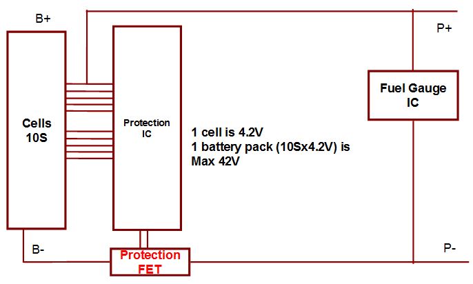
What is the MOSFET selection guide for VDS and ID for 10S battery pack? Each cell is 4.2V.

Thanks.

  • Hong
    Which FET are you referring to? The bq34z100EVM contains the BOM for the components that we have evaluated and it will support 10S.
    Tom
  • Hi Thomas,

    I mean the FET to control the switching of charging.

    There is another question, if there is 3 battery packs (10S for each) in series, should we choose a MOSFET to support the 3 battery packs?

    Thanks.
  • Hong,
    If you could provide a schematic or block diagram with the MOSFET implementation, then this would help to understand how this is being configured. You should be able to connect the three string in parallel and then to BAT+ and BAT- of the gauge. The strings should track one another in voltage.
    Tom
  • Hi Thomas,

    Please refer to the block diagram for better understanding.

    1 battery pack designed with 10S battery, 4.2V per cell. Total 42V.

    There will be 6 battery pack in series. Means total 252V for whole system.

    My question is when we selecting protection FET, we should consider 42V as max voltage support or 252V as max voltage support?

    Thanks.

  • Hi Thomas,

    Any advice?

    Thanks.
  • Hong,
    Are you planning to cascade these packs to create the 252V pack? e.g. P+ connected to P- of the pack above it? if so, you will have to use I2C isolator devices to communicate with the bq34z100-G1 device, since some of them will not be referenced to system ground. Also, which protector IC are you planning to use? I will pass the e2e string over to the protector forum for a FET recommendation and comment on whether this architecture will work for the protector.
    Tom
  • Hi Hong,
    If you stack 6 batteries and any one can protect, you need to accomodate the system voltage (252V) for each FET, plus any expected transient. You also need to keep the system voltage or resulting current at a safe level for the individual protection IC.
    The other approach is to send the signals from the individual protection ICs to a common protection switch for the system, but that is a different structure which does not have protection on the individual batteries.
  • Hi Thomas,

    Thanks for your advice.

    Regarding the I2C isolator, we have not looked into it yet. Is the I2C isolator needed per pack or as a system solution which can be added outside the battery packs which means inside the device side?

    For the protector IC, Ricoh R5432V with over charge current (OCC) function protection selected. As per confirmed in another post, TI do not have OCC function protector IC at this moment.

    www.e-devices.ricoh.co.jp/.../r5432v-c-e.pdf

    Thanks.
  • Hi Sir,

    Thanks for your advice.
  • Hi Sir,

    Regarding the I2C isolator, we have not looked into it yet. Is the I2C isolator needed per pack or as a system solution which can be added outside the battery packs which means inside the device side? Please advise.

    Thanks.
  • You will need to use one isolator per bq34z100-G1, because they will have different ground references.