This thread has been locked.

If you have a related question, please click the "
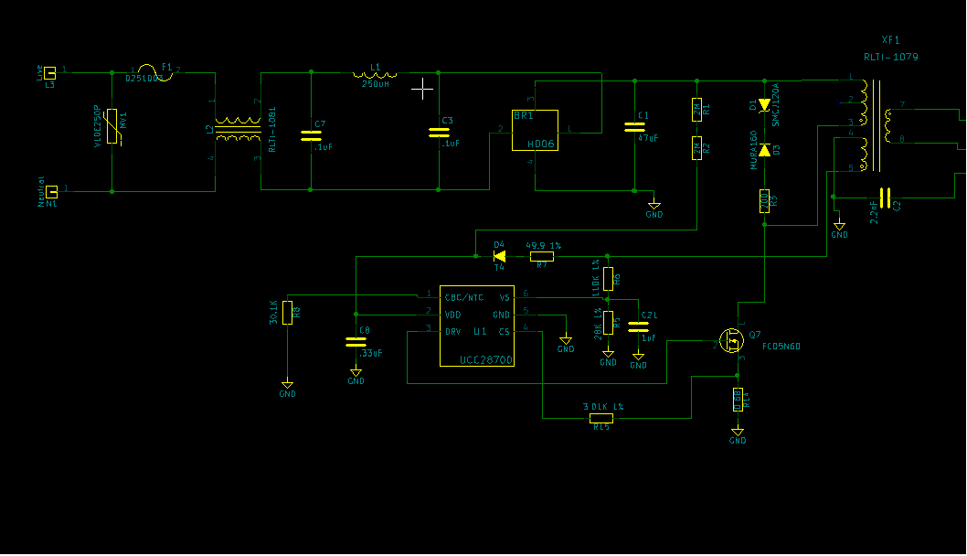
Ask a related question" button in the top right corner. The newly created question will be automatically linked to this question.

UCC28700: UCC28700/ RCS resistor blows everytime I turn on.

Part Number: UCC28700

I am using the UCC28700 chip for a 5V 4.2A circuit. Every time I try to turn the circuit on the RCS resistor blows up. What could the potential problems be? I will add my schematic. The resistor value is R14 in my schematic.

  • Hagen,

    I have forward your question to the Application Team who should be responding shortly.
  • Hi Hagen, I don't see any obvious errors in your schematic, so I think there must be a build or component error or something like that somewhere.

    I would recommend starting the unit up at a low voltage, possibly from a DC source and observing that the waveforms are as expected.

    See this video which explains what you should expect to see as you start up a UCC28700 based design.

    Hopefully if you follow through this it will help you accertain where the issue is.

    Thanks

    Billy

  • what is the transformer?
  • Hello Hagan,

    A review of the schematic diagram is a good place to start for debug, but it doesn't tell the whole story. As Billy Long suggested, there may be other problems not reflected on the schematic. Hopefully, the start-up procedure video that he suggested can help you with your debug.

    The "blow-up" symptom of failure indicates significant rapid overheating. Please verify that the power rating of the part used at R14 is suitable to the expected loss. Also verify that the part placed at R14 is the resistance value that is shown on the schematic. Presuming for the moment that it is properly rated, that implies excess current which points to the MOSFET being on too long.

    I discount transformer saturation for now, because I'd expect the peak current limit to cut the on-time very short, and the circuit should end up in UVLO "hiccup" cycling. Instead, I suggest to examine the CS input for proper signal. Be sure that it is not shorted to GND (its neighboring pin) through a solder-bridge or assembly mistake. The MOSFET is turned off when the CS voltage reaches Vcst(max) which is 0.75V in the UCC28700. If CS is grounded or stuck low, Vcst(max) is never reached, the second-level current limit won't work, and the MOSFET will stay on too long. There is a finite timeout for on time, but it is too long for all but the lowest input voltages.

    There is one other issue with this design: the schematic shows C21 (1uF) cap on the VS input. This cap should absolutely be removed! The VS input relies on the detection of several dynamic aspects of the auxiliary winding waveform and a capacitance on VS will obliterate all of those aspects. At most, a few picofarads can be tolerated at this node if necessary to suppress some noise, but no capacitance is preferred. I'm not sure if this has anything to do with R14 blowing up, but the 1uF has to go, regardless.

    I hope these points help you get your circuit working. Please let us know if this answers your question(s).

    Regards,
    Ulrich
  • Ulrich,

    this chip seems like the next gen of the UCC2863x, does it have the error code on the NTC pin as well?

    i consider it an extreme oversight to have not included the error code details in the data sheet. I, off hand, do see in the data sheet a fault protection section, but, as in the UCC2863x, no details. I was only in these forums that it came out that there were error codes emitted on the NTC pin that included various shorted pins, over/under voltage on both supplies and output etc on this pin.

    in design these have been invaluable, and i could see good use for them in production troubleshooting as well

    Dan
  • Hello Dan,

    Despite the apparent sequence of part numbering, the UCC28700 predates the UCC2863x series by a few years, and these families were developed by different internal groups with different design goals. The UCC28700 and subsequent -7xx family of controllers are predominantly analog-based and do not provide any error codes. The UCC2863x family contains analog with expanded digital control which allows it to provide additional application features, as well as the error codes.

    Regards,
    Ulrich
  • Thanks, I will try removing this capacitor.

  • sheesh! i was so focused on not knowing what the transformer was i did not even see that cap lol

    Ulrich: that cap would have been flagged as a short to GND on the UCC2863x wouldn't it have?