This thread has been locked.

If you have a related question, please click the "Ask a related question" button in the top right corner. The newly created question will be automatically linked to this question.

BQ78350-R1: Calibration Problem

Part Number: BQ78350-R1
Other Parts Discussed in Thread: BQ76930, BQ78350, , BQSTUDIO

Greetings

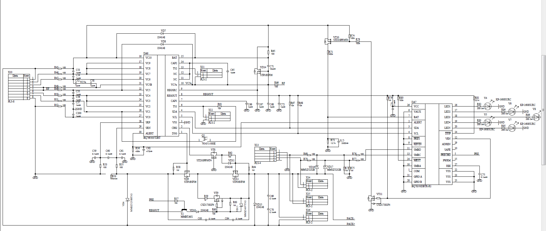
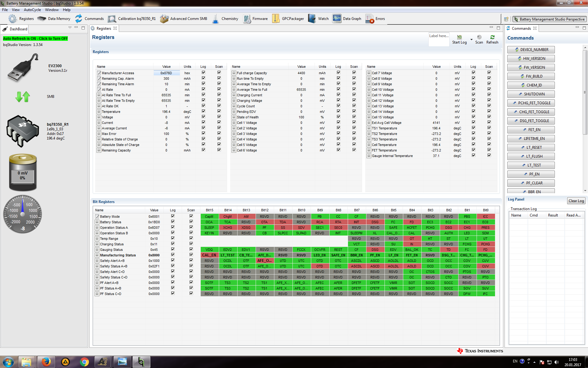
So, I'm trying to calibrate my BQ78350-R1 using Battery Managment Studio, but i've confronted problem.

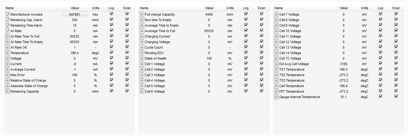
While reading ManufacturerData() I can't properly read any cell voltage. All I get is zeros at any cell, what in fact is wrong. Where could be a problem and how to solve it?

I attached screenshots to show my situation.

Thanks for helping

Anton Kanyshev

  • Hi Anton,

    Check to if there's PF. The temp is 196C, which would trigger a PF.

  • Hi, Damian

    Here are PFAlert and PFStatus. All zeros, as I can see

  • Anton,
    Can you export an srec from your pack and send it? This looks like a setup problem.
    Tom
  • Thomas,

    Probably, this is the file you asked for

    https://drive.google.com/open?id=0B13jsAOtJTUkRlE5dGpwcDB0Tjg

    Thanks for helping

  • Anton
    We are restricted from using Google drive. Please attach the srec to this e2e string.
    Tom
  • Anton,

    I checked the srec fie and only three cells are enabled in the AFE Cell Map register. The register should be configured like this.


    That still does not explain why your gauge does not report any cell voltages. I discussed this with the apps engineer who supports the AFE device and he said that it looks like the top die in the bq76930 is not powering up. The bq76930 is a two die MCM. Please check a couple of things to see why it is not powering up.

    • Make sure that the thermistor, or 10k resistor,  is attached between TS2 and VC5x.
    • Check to see whether the CAP2 capacitor could be shorted.


    There are a few problems on the schematic.

    • The trace going from R45 to R65, VT10 and R74 should be connected to the VC10 side of R45. Connecting it to the device side will cause cell voltage measurement errors for Cell 6.
    • The LEDs are not configured properly. The cathodes should be connected to the LED pins on the device. You can reference one of the bq739xx EVM User's Guides for the proper implementation.

    Tom

  • Tom,

    The register now properly configured and, as expected, this did not change my situation.
    I checked thermistor and CAP2 capacitor. So - 10k thermistor properly attached and CAP2 capacitor works well - it's not shorted.

    Did I understand you correctly? The trace R45-R74 should begin between VC10 pin of BQ78350 and R45, not between R45 and battery pack? 'Cause it is the way how it's connected at the moment.
    Also, thanks for noticing LED problem, I will check it out, but first of all - voltage problem should be eliminated.

    I am most grateful to you for helping me.
    Anton
  • Tom,

    I also encountered some weird witchcraft. At the moment when I'm changing the ManufacturingStatus () [CAL] bit from off to on, the BQ78350-R1 showing me adequate voltage. I'm applying 19 V and chip is showing 21600. I attached screenshot of exact moment and right after I refresh registers screen

    Hope it helps to understand reasons of problem,
    Anton

  • Hi Anton,

    At the top of the schematic, the connection line or wire from R45 going off to R65 and the other circuits should connect to the cell side of R45, not the device side.  I agree with Tom, the present connection may not prevent operation, but would lead to improper top cell voltage measurement.  With 19V on the battery you might be sure you maintain about 9V across C71 and C68.

    The thermistors should be connected at boot.  After boot C65 should have approximately 3.3V.  If not, the 0 voltages and the 196 deg c may occur. 

    C68 and C71 are shown as different values on the schematic.  Normally these should be large and the same value. Be sure you provide cell voltages when testing the board.

    The 100 ohm input and power filter resistors seem rather small for the bq76930, 1k is more typical.  The 1k value is helpful during short circuit to prevent discharging the power filter capacitors. The 100 ohm is not likely to prevent normal voltage reporting unless the IC has been damaged.  You may look at the bq769x0 Family Top 10 Design Considerations app note.  A diode in the REGSRC path will prevent loss of power for communications and the gauge during short circuit also, see section 9 of the apnote.  With 6 cells, consider if you can remove VD14 and obtain the REGSRC supply from PACK+ with a diode and filters.

    You might look at the SDA and SCL lines during operation to see if the SDA line is mostly 0 during communication as would be indicated by the 0 V cell data.  You should see a burst of transactions every 250 ms with a lot of idle time.  The SDA line should not be fixed low since you are reporting ASCD and AOLD in the safety status registers, these would come from the bq76930 as "1" on the bus.  The sense resistor R54 appears open on the schematic, this may be a cause of those faults.

    On the schematic, X13 references the SMBus to GND, the same as the gauge.  However VD16 and VD17 connect to PACK-.  When the FETs are off, PACK- may pull up or down on the SMBus lines and interfere with the communication.  If there is a load on PACK, PACK- may pull the signals up to a high voltage and damage the 100 ohm resistors or IC pins.  Common methods to avoid this are to use an isolated interface, switch the SMBC and SMBD as shown in Using the bq78350  figure 10, or use high side protection FETs. Figure 10 of course prevents talking to the gauge during a fault.  For troubleshooting you might try to remove VD16 and VD17 or temporarily short PACK- to GND to see if your situation changes.

  • Hi Anton,
    Another area of caution. The part number on the schematic for DA6 is bq7693007DBT, this is a 3.3V REGOUT part, the bq78350-R1 is a 2.5V part. Be sure you have a version of the monitor installed at DA6 which is compatible with the bq78350-R1.
  • Hi again


    So let me go through each step:

    1) Problem with 3.3V REGOUT was noticed by me at the first place. I reduced voltage at REGOUT line between BQ7693007DBT and BQ78350-R1 to 2.6V by applying serial diod with voltage drop 07V. So BQ78350-R1 is receiving needed voltage at VCC pin and R67 and R68 pulling SDA and SCL to 2.6V. By this way, I'm achieving suitable voltage at power and logic lines

    2) For further troubleshooting I fixed line around R45. Now it starts from cell side;

    3) C68 and C71 now both 10 uF;

    4) All 100 ohm input and filter resistors replaced by 1 kohm resistors;

    5) Checked voltage across C71 and C68 - stable 9.2 V, C65 has solid 3.3V;

    6) Diode in REGSRC would be usefull, but as I can see, it will not help in current situation, so I let it be as it is for now;

    7) Checked SDA and SCL lines during operation - they are completely healthy. You can observe SDA at the end of my reply;

    8) PACK- and GND already shorted for troubleshooting reasons.

    You can guess the result - still 0V and 196 deg.

    I am most grateful to you for helping me.
    Anton

  • P.S. - Also, here is SCL and SDA

  • Hi Anton,
    I expect the bq7693007 is the issue. If you zoom out on the scope the I2C transactions likely fill the 250ms timeline rather than being a short burst. Although you have dealt with the 2.5V supply voltage for the bq78350-R1, it only looks for the monitor at address 0x08. See the bq78350-R1 Technical Reference Manual introduction page 10. Install a bq76930 version with address 0x08, normally an 00 or 01 version. The address 0x18 version parts are sometimes desired when the designer is using a MCU rather than a gauge.
  • Hi, WM5295

    Looks like this is the case and problem is in address. But therefore I've got couple questions:

    1) How did I manage get any correct data? As you can observe in my previous messages, BQ78360-R1 showed voltage at the moment of changing CAL_EN. Now I don't know how it's possible.

    2) Is there imaginable way to get into BQ73690 EEPROM and to change address from 0x18 to 0x08? Or to change searched address at BQ78350-R1?


    I'm attaching screen of LogicStudio showing what happening at I2C between tandem, so descendants may see where is the problem.

    Thank you for contributing so much to my problem

    Anton

  • Anton
    The bq78350-R1 is also measuring the battery voltage with the circuit connected to the BAT pin. This could be what is reported on the bqStudio screen. The I2C address cannot be changed from 0x18 to 0x08 in the bq78350-R1 without a firmware change.
    Tom
  • Tom,

    Yes, probably this is the reason. Thanks for helping in this problem, but it would be nice, if such significant weakness as permanently stored address will be showed in BQ78350-R1 datasheet at the first place, instead of saying that "bq78350-R1 Li-Ion and LiFePO4 Battery Management Controller and companion to the bq769x0 family". Think about it - there is at least 252 pages of documents about bq769x0 and BQ78350-R1 tandem but only 3 strings about address weakness. And those strings not even in datasheet, only in Technical Reference at 10-th page.

    Doesn't look quite right for me, how 'bout you?

    Anyway, it’s hard to find words to express my gratitude to you, Tom, and WM5295.
    Thank you, again.
    Anton

  • Several versions of the bq769xx devices were released to allow the user flexibility in choosing a controller for the device. We offer the bq78350-R1, but it is limited to supporting the devices that offer REGOUT = 2.5V and I2C address set to 0x08. We can add more clarification of these restrictions to the bq78350-R1 documentation, if that would help.

  • That flexibility is without doubt wonderful feature and it's really great that you offer such variety of devices. But it is sure enough important to give a warning to every future users of bq78350-R1, thus you will eliminate such problem ever after.
    Thank you for understanding