This thread has been locked.

If you have a related question, please click the "Ask a related question" button in the top right corner. The newly created question will be automatically linked to this question.

Fully autonomous single cell Li-Ion charger w/ USB enumeration (support for SDP, CDP, DCP, BC1.2 compliant)

Other Parts Discussed in Thread: BQ25895, TPS61236P, TPS2514A, TPS61235P, TPS2559, BQ24392, TS3USB221, BQ25895M, LP2985, TPD1S414, TS3USB221A, TPS61230A

Dear all,


we would like to build a fully autonomous single cell Li-Ion charger w/ USB enumeration (support for SDP, CDP, DCP, BC1.2 compliant) with fuel gauge measurement.

But the trick is that the battery pack should be fully autonomous from the host system, meaning charger should evaluate the USB source, set the proper charging current and then leave the USB data line for communication with the host (so not to interfere with USB line). All this should be done without a use of MCU (if possible). Solution will be used in 2 design:

  1. As a battery pack for mass storage device (build in acupack)

  2. As an external auxiliary power source = rugged USB power bank with fuel gauge (for external power)

So therefore as you can see, in 2nd case, we will not have a MCU available so it should be autonomous.


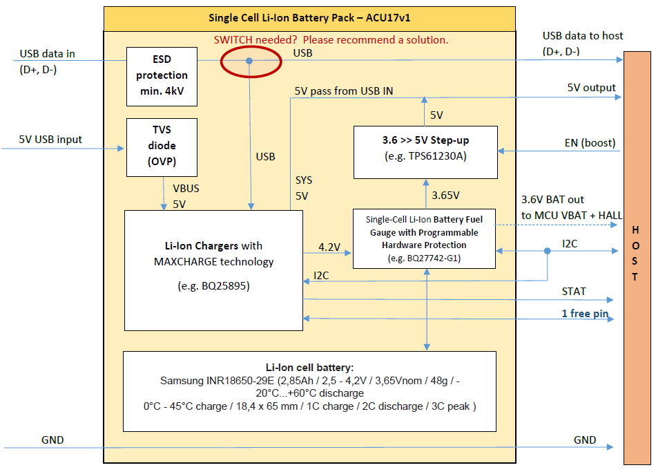
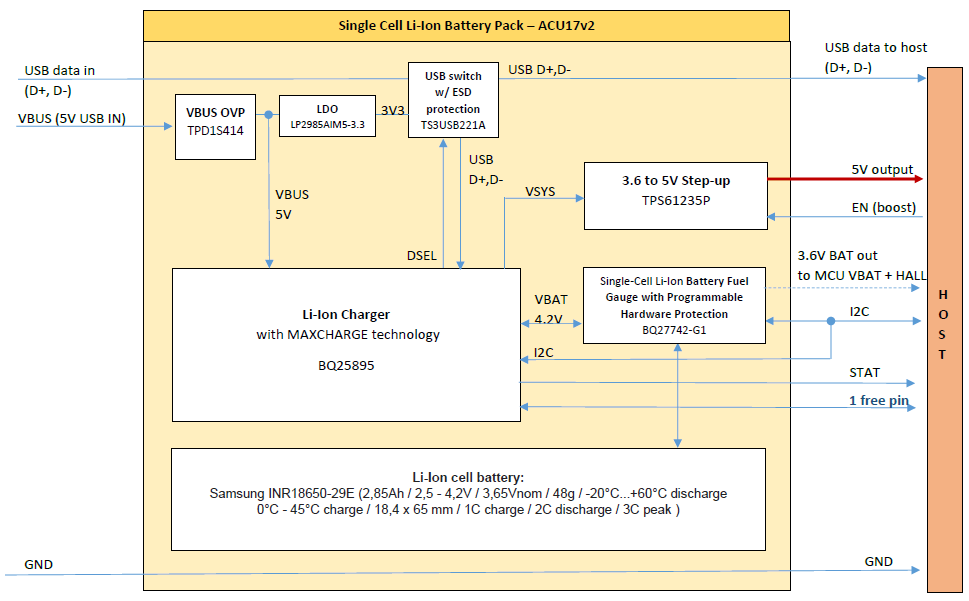
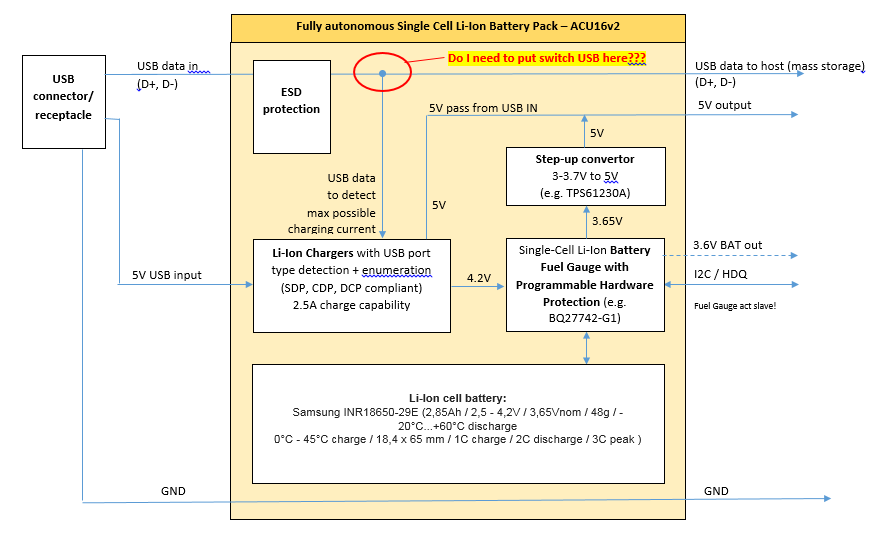
The block diagram for the ACUPACK should look like this:


Expected parameter of the system: 


Main features:

  • Fully autonomous Single Cell Li+ ACUPACK w/ on-board charger, step-up, protection and fuel gauge data w/ I2C output

  • Capable to charge and power up the host at the same time

  • Capable to pass USB data to the host (for mass storage device)

  • Quick charging (up to 2hrs)

Input:

  • Single input only – 4 pin connector w/ USB data lines (ESD protected)

  • 5V from USB only (but with min 15V OVP protection)

  • Automatic USB type or and adapter detection (support of SDP, CDP a DCP) + USB enumeration

  • Support for all charging currents:  100mA, 500mA and 2.5A (full possible current)

Output:

  • 5V / 2A continuous

  • 2.5A peak (if needed)

  • Protected against short-circuit

Communication / data:

  • I2C™ / HDQ Interface Formats for Communication with Host System (Fuel Gauge)

  • USB data pass from IN connector to the host

  • 1 pin for CHARGING OK/pre-CHARGING

  • 1pin for POWER GOOD/system status?

Protection of battery (cell):

  • Hardware-based Safety and Protection:

    • Overvoltage (OVP)

    • Undervoltage (UVP)

    • Overcurrent in Charge (OCC)

    • Overcurrent in Discharge (OCD)

    • Short-Circuit in Discharge (SCD)


2 major questions we have:

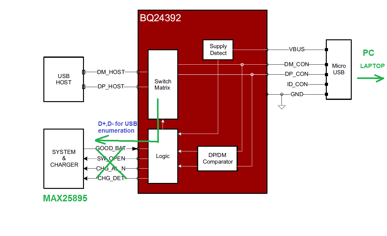
1) How to evaluate USB without interfere w/ USB data line/data (w/ no MCU present)

2) Do I need USB switch? (again, do I need to put MCU to the board or can it be w/ no MCU present)?

Can you recommend a TI charger that would fit our design?

Thank you in advance.


With kind regards,

Daniel

  • Hello Daniel,

    I would highly recommend looking at the bq25895. It is a very capable charger and it performs full BC1.2 USB enumeration which would handle negotiating power from the source.

    Regarding how you are accomplishing the output OTG power I would recommend looking at the TPS61236P or TPS61235P combined with the TPS2514A. Together these parts will accomplish the following.
    -Boost the battery voltage up to 5V - 5.5V for OTG
    -The TPS61236P or TPS61235P has an integrated constant current circuit which eliminates the need for a part like the TPS2559 saving both cost and efficiency lose. (This current limit will help protect against output short circuits)
    -The TPS2514A then serves as the down stream negotiator so that it will negotiate with whatever is connected to the OTG port what type of USB power port your product is an how much current it can support which will match the current limit you designed into the TPS61236P circuit
  • Hi Ryan,

    many thanks for your reply and recommendation of BQ25895. This chip looks good and we can use it in our design.

    Regarding OTG, I'm not sure we understood each other. We do not plan to use OTG function so therefore topology as you proposed will not probably fit our design.

    Here is what we need to build - a device that you can be charge from USB (e.g PC or laptop) and PC or laptop can communicate with the HOST (Cortex MCU) at the same time (while charging). Look at it as a MP3 portable device - you can charge it but at the same time upload your music files to mass storage device. Now we want to use the same design (same board) in our external acupack, where there is NO HOST mcu, so the charging needs to run autonomously - pretty much like you charge external powerbank from your laptop and then use it to power up some other devices just with 5V output (no USB comm needed here).

    We were thinking of new topology (please see below) with your recommended part BQ25895, but as we can see, there is no possibility to put both USB BQ25895 data lines (for USB enumeration) and USB host data (for mass storage) parallel together. Is there a way how to solve it? Can we use a switch? I looked at some switches, like (TS3USB221) but it needs an intervention from external MCU and it acts more like multiplexing which I am not sure it actually could work in our case. Also there is a part BQ24392, but it does not have an USB output for charger, obviously it is for a different use and I assume it cannot work w/ BQ25895.

    So what we would need is the part witch such functionality:

    Do you have an idea how to solve it the entire design? Any recommendations how to adjust the schematics to achieve the functionality we want?

    Thank you.

    with kind regards,

    Daniel

  • Hey Daniel,

    As Ryan suggested, the bq25895M is a suitable part for what you are trying to accomplish.

    For your full system functionality, you would also need something like the TS3USB221 USB switch to release control of the DPDM lines from the charger to the USB host.

    The bq25895M includes a DSEL pin that is used solely as an output for a multiplexer select pin for a part like the USB switch previously mentioned. If an SDP or CDP is detected, it will pull HIGH to switch control. If a DCP, MaxCharge, or other type of adapter is used, it will pull LOW.

    As for the 5V SYS voltage from the charger, that is something the part cannot provide from the SYS pin, but I'm sure you could design some simple pass circuit to allow 5V USB to the rest of your system.

    Please note that the default battery regulation voltage on this part is 4.352V, so you will need to set the VREG bits back to 4.208V for your specific battery. 


    Hope this helps!

    Regards,
    Joel H

  • Hi Joel, Ryan,

    thank you very much for clearing this up and for your suggestion. This looks good. I updated the block diagram (below), adding TPD1S414 (for VBUS OVP), LP2985 (LDO for SWITCH) and TS3USB221A for switching USB line.

    Based on your recommendation I also switch from TPS61230A to TPS61235P to have a current protected 5V output.

    Joel, you wrote: the default battery regulation voltage on part BQ25985M is 4.352V, so you will need to set the VREG bits back to 4.208V for your specific battery.

    Can I just use BQ25895 instead? Based on the reply on E2E, BQ25895 should do 4.2V by default: 

    Is the voltage really just an only difference of parts BQ25989 and BQ25895M?

    Last topic:
    as for the 5V SYS voltage from the charger, that is something the part cannot provide from the SYS pin, but I'm sure you could design some simple pass circuit to allow 5V USB to the rest of your system. >> You are right, I made a mistake in my block diagram.

    What we need is the capability of powering the HOST and the charging AT THE SAME TIME (obviously it will take longer to charge the battery as some current is used to keep the HOST running).

    Here is the parameters we need to meet:

    - Iout to the HOST while charging - 0.8A (@5V) average - in case of 1.5A charger or higher
    (in case of 500mA charger, host can shut down some peripherals to lower current consumption so that the charger is able to use some juice to charge the battery)

    - Iout to the HOST while running from the battery - 1.5A average, 2.5A peak (few ms]

    We will be using 5V/3A dedicated charger (wall charger) or laptop USB port (0.5A/1.5A).

    Is BQ25895M able to seamlessly transfer power from its input to VBAT (to charge the battery) and to VSYS (to the load - in this case 5V step up for the host)?
    From your experience, is it OK to use the configuration in my block diagram below or would you go for 5V VBUS pass to the output (discrete solution as you mentioned). If MOSFET discrete solution is the better solution (e.g. more efficient), can you recommend some TI parts (MOSFETS) that are for space constraints applications and can do the job? Maybe you can recollect some reference designs that I can look at and inspire from.

    Thank you.

    With kind regards,

    Daniel