This thread has been locked.

If you have a related question, please click the "Ask a related question" button in the top right corner. The newly created question will be automatically linked to this question.

UCC2895: 6kW Half bridge phase shift Unbalanced Primary current

Part Number: UCC2895

Hello all,

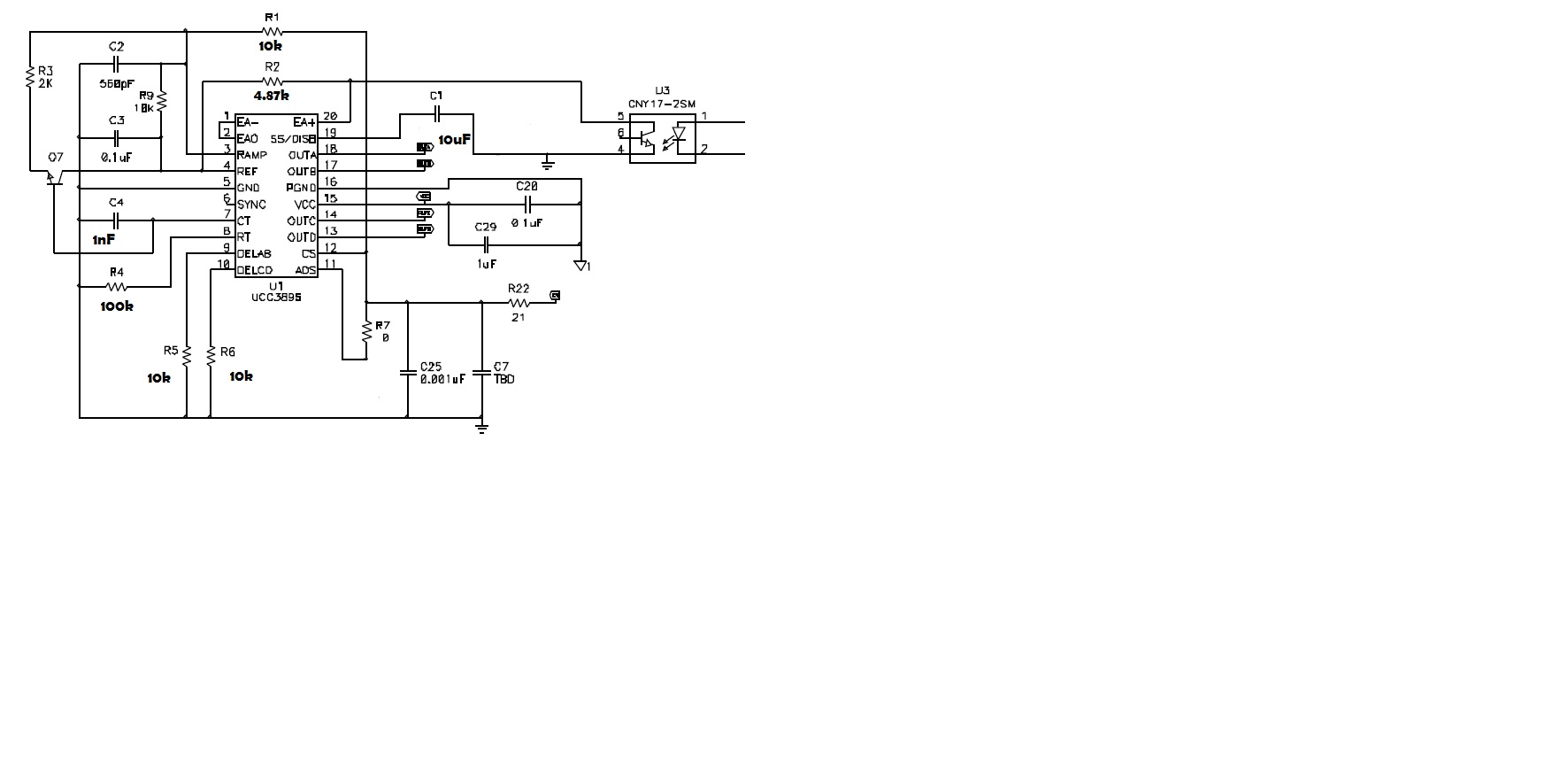
I am using the Phase-Shift PWM Controller UCC2895 for a DC/DC full bridge ZVS converter of 6kW with a fixed frequency of 50 kHz.

Vin=400V and Vout= 100V to 400V

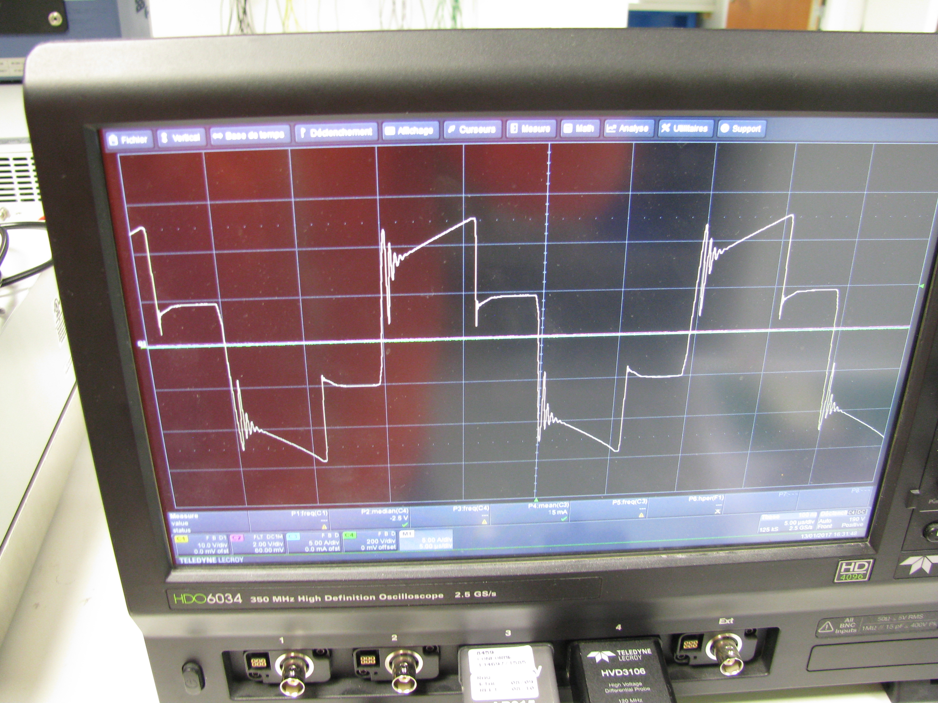
When I increased the output power, the primary current show an unbalanced wave form.

I am using gate drive transformer like in sluu421.

I improved with a better compensation loop but I still have the problem.

At the end the transformer is saturated!!! (On the picture the transformer is begining to sature)

Have you got a idea of what I have to modify to solve this issue?

Thanks in advance,

Best Regards,

Pierrot

  • Hi Pierrot,

    An AE will respond to your question but, it may be delayed until Monday.

  • Hi Pierrot,

    My first thought is the converter operate in voltage mode control rather than current mode, because in current mode control the PWM comparator terminates the present switching cycle when the peak current reaches the current demand point set by the EA inputs. This feature is present on both transformer polarities (OUTA/OUTC and OUTB/OUTD) and will prevent any DC flux in the transformer, this means that there is no possibility to have an imbalance in the transformer currents. But in voltage mode control the EA output controls the duty cycle directly  – small differences in propagation delays etc etc will unbalance the duty cycle seen by the transformer. The result will be a nett dc flux in the core.

    Too much slope compensation reduces the benefits of PCM control, the magnetizing current in the primary of the transformer caused by the magnetizing inductance(Lm) will also add some slope compensation and needs to be accounted for when adding slope compensation. As Lm reduces, the increasing magnetizing current becomes an increasing proportion of the signal at the CS pin. If the magnetizing current increases enough it can swamp out the current sense signal across RCS and the converter will operate increasingly as if it were in voltage mode rather than current mode control. To ensure that the converter is not operating in voltage-mode control, it is recommended that you reduce the slope compensation and choose a transformer for your design with larger magnetizing inductance.

    Thanks
    Oliver
  • Thank you very much Oliver for your answer.

    I will change my slope compensation to stay in current mode.

    I will let you know

    Thanks

    Pierrot

  • Hi Oliver,

    I changed R1, C2, R3 and now it is balanced.

    Thank you very much for your quick help!!

    Best regards,

    Pierrot

  • Hi Oliver,

    I have a question on the schematics used on the SLUP102 for example. When I look at the waveforms, they are very clean. I cannot have the same waveforms if I does not add 2 diodes between the transformer and the inductance as you can find on the schematic of sluu421A.

    If I does not add these diode, I have a big oscillation on the primary voltage and primary curent.

    Do you have a idea why we cannot find these oscillations?

    Thanks you in advance

    Best Regards

    Pierrot

  • Hi Oliver,

    I do not know, If I have a other question, if I need to create a new post or not.

    When I use my half bridge in hard switching without the inductance, the balance is OK now. But when I add the inductance in série with the primary I still have a unbalanced primary current waveforms.

    Is the current mode control can have a problem with the zvs schematic (inductance in série with the primary)?

    And I have a other question on the schematics used on the SLUP102 for example. When I look at the waveforms, they are very clean. I cannot have the same waveforms if I does not add 2 diodes between the transformer and the inductance as you can find on the schematic of sluu421A.

    If I does not add these diode, I have a big oscillation on the primary voltage and primary curent.

    Do you have a idea why we cannot find these oscillations?

    Thanks you in advance

    Best Regards

    Pierrot
  • Hi Pierrot,

    If you want to control a half bridge stage then you'd better use voltage mode control. Because the peak current mode control is inherently unstable and has a tendancy to go into oscillation due to imbalances. This is a characteristic of the current mode controlled half-bridge topology and more detailed reason is discussed in the following papers:

    www.ti.com/.../snva607.pdf
    www.how2power.com/.../H2PToday1204_design_TexasInstruments.pdf

    For your second question: there is a potential for high voltage ringing on the secondary rectifiers, caused by the difference in current between the transformer and the shim inductor when the transformer comes out of freewheeling. Diodes D5 and D11 in the SLUU421A provide a path for this current and prevent any ringing by clamping the transformer primary to the primary side power rails. This protect the synchronous rectifiers from an over voltage. If you do not add these diodes, you will see the ringing.

    Thanks
    Oliver
  • Thanks you Oliver for your answer,

    I am so sorry, I made a mistake in my last message, I would like to say full bridge and not half bridge.

    When I use my full bridge in hard switching without the inductance, the balance is OK now. But when I add the inductance in série with the primary I still have a unbalanced primary current waveforms. I have to add a capacitor in serie with the primary.

    Is the current mode control can have a problem with the zvs schematic (inductance in série with the primary)?

    Thanks you in advance

    Best Regards

    Pierrot