A related question is a question created from another question. When the related question is created, it will be automatically linked to the original question.
If you have a related question, please click the "Ask a related question" button in the top right corner. The newly created question will be automatically linked to this question.
Could you provide a little more information such as the input voltage and any dimming requirements you have? But the short answer is yes, if you have a good layout to minimize noise coupling you can run two in parallel.
But you may also want to consider the LM3409 as it is a controller and could do 3A with a single driver.
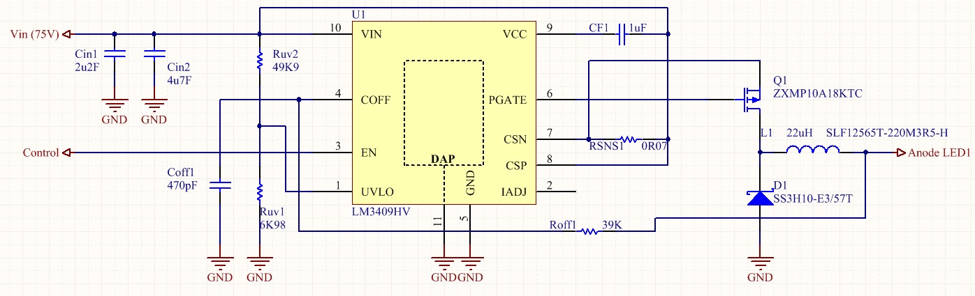
In colaboration with Paulo I'm working on this project and I designed a circuit in order to make a driver for a string of LEDs with an IF= 3A.
The circuit is that one I send below:
To control the output I apply 5V on the "Control" input, the pin 3 of LM3409 (EN), my itention is to turn on the LEDs when I apply 5V on "control, and turn off the when I remove this signal. The max frequency that I need to do the switching is 30Hz, by other words, I need to turn on and turn off the LEDs 30 times per second.
I don't know what I did wrong, but nothing happens when apply the 5V on pin 3 of LM3409 ("Control").
Does this happen when you pull EN high and keep it there, or are you using the PWM signal? If it's the first case there is likely some manufacturing/soldering issue because it should turn on and work fine. But if it is the second you probably do not want to use the EN pin. If EN is low long enough for VCC to discharge it will go into low power shutdown mode and the response on the next EN high will be delayed. If that is the case you could use the high/low signal on the UVLO pin (use a schottky with the anode on UVLO and apply the signal to the cathode) and it will work the same except it will not ever discharge VCC and go into low power shutdown. Then the response is much better. Generally anything under around 120Hz you will be better off using the UVLO pin.
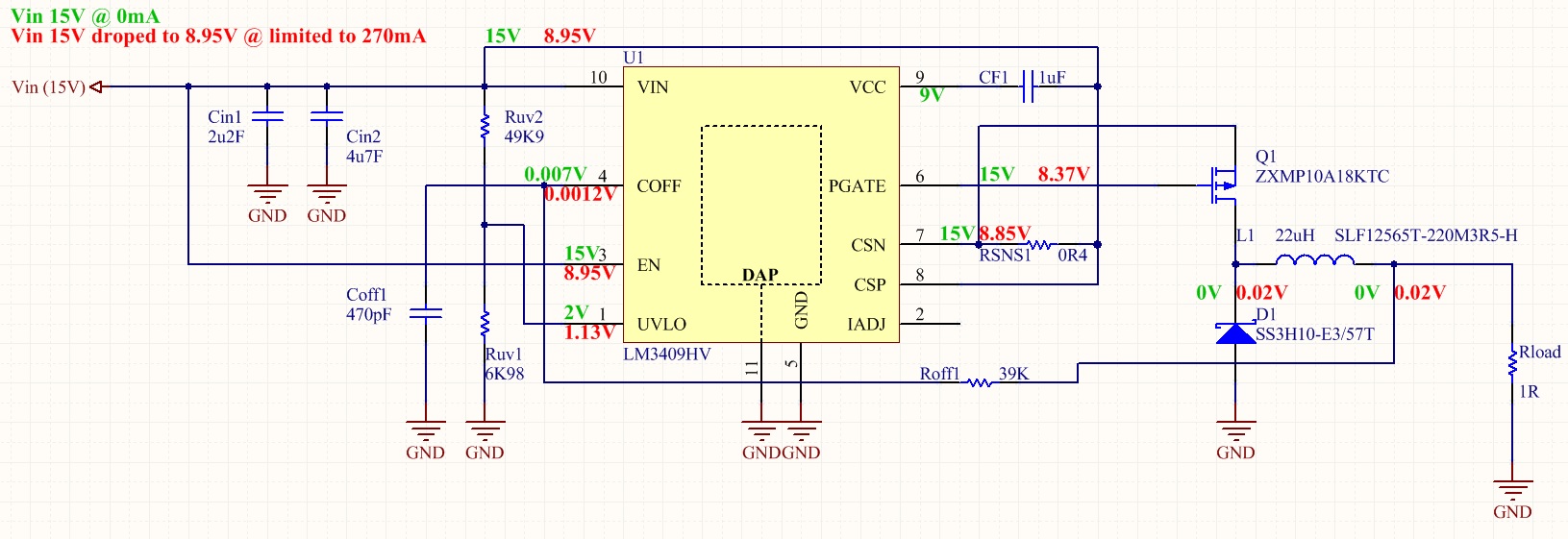
I checked all soldering issues and all is OK, I don't use dimming with PWM, I just want to put the circuit in CCM (continuous mode). I connected the EN pin to the Vin as you can see in the picture below. I supplied the Vin with 15V, only for test and connected a 1 ohm resistor as load. If power up the circuit with the EN to the Vin (15V), nothing happens, I measured the voltages in all nodes and I wrote on schematic in GREEN. If I disconnect the EN pin from 15V and connect to the ground (0V) and connect again to the 15V while the Vin is powered up the circuit sink a lot of current, but I limited to 250mA more or less to avoid some damage. In this case I measure the voltages that you can find in RED. It seems that the PFET never switch on, what I did wrong?
First, the way the LM3409 starts up it will turn the FET on until full peak current is reached. Your peak current setting is over 250mA so you will likely clamp the supply. It looks like your peak current setting is over 600mA. If you want to be safe you can set a current limit but I would make it at least 1A.
Second, that 600mA or so will only put about 600mV across the 1ohm load even if the supply isn't current limited. That will never charge COFF to its 1.24V threshold. So after you don't current limit the supply it will just operate in maximum off-time mode. For correct normal operation the output voltage needs to be greater than 1.24V.
Thanks for your support and quick answers, but I still have problems.
I did some changes in order to start the circuit working.
With an Rsns=0.4ohm the current is I=200mV/400mohm <=> I=500mA, isn't it?
I changed the load for a 4.4ohm resistor, now I should have a Vo=500mA*4.4ohm <=> Vo=2.2V, so greater than 1.24V.
Also I limit now the total current, up to 1A.
With this conditions and when I turn on the power supply (15V), the EN pin is connected to the Vin (15V), the power voltage drops to more or less 9V and reach the maximum current (1A), the PFET never turns ON, the current on load is near zero and the PFET gets very hot.
Other thing that I saw is the voltage on gate of the PFET is always positive near 15V, to the PFET turns ON is necessary a negative voltage as far as I know.
I don't understand is going wrong. Have you any tip to help me?
The LM3409 actually regulates peak inductor current so that is what you are setting with the current sense resistor. Also, with IADJ open the peak CSP-CSN voltage will be 250mV. So you are setting a peak current of 625mA and the average output current will be dependent on the inductor current ripple.
As for the behavior you are seeing it sounds more like something may be damaged. Have you tried replacing the IC and the FET? Perhaps something was damaged during earlier testing?


