This thread has been locked.

If you have a related question, please click the "Ask a related question" button in the top right corner. The newly created question will be automatically linked to this question.

BQ34Z100-G1: I cannot finish the calibration

Part Number: BQ34Z100-G1
Other Parts Discussed in Thread: BQSTUDIO

Dear all,

I designed my PCB (portable device, 1 Li-Ion cell of 3.7V, 1100mAh) with the gas gauge BQ34Z100-G1. I followed the instructions from the document SLUA334b.pdf (with close Qmax value) and I made 4 cycles so far but the "Learned Status" is still at 0x04 and the MaxError is still at 100%.

I always respected the relax times... I did the calibration (Voltage, Current, CC offset and board offset).

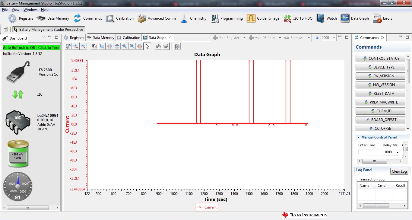
What I noticed is sometime, when my circuit is idle, I saw the current going to -1ma (which is very low but the current consumption should be 0mA when my circuit is idle). Do you think I can have a CC offset or board offset issue? As well, I put the deadband current to 1mA (now 2mA), would it be a problem for the learning phase?


Moreover, I use a protection circuit (BQ29700) that switches the MOSFET off when the battery voltage drops below 2.8V and I always wait on this event. This could be another issue or is it OK ?

Best,

Christian

  • Christian,
    The deadband should not be affecting the optimization cycle. Please attach the log file an I will check it. Attach an srec from the pack as well and I will check your parameters.
    Tom
  • Files.rar

    Dear Tom,

    Here are the files, I hope I uploaded them correctly... there is a discharge and a charge in the .log file.

    Best,

    Christian

  • Christian,
    The log file shows that the pack was probably discharged into a shutdown condition and this will abort the optimization cycle. I tried loading you srec file, but it was corrupted. Are you seeing any communications issues with your bqStudio? What is your Cell Term Voltage? You should keep it at 3V or above for a single cell and you should not discharge below 3V.
    Tom
  • Dear Tom,

    Thank you for your response. Sorry for the late answer, my weekends lasts 3 days (Fri-Sat-Sun).

    Yes, I have some communication issues with bqStudio, I don't know why. I put 2x 10K pull-up resistors for SDA and SCL as suggested in the datasheet. Sometimes I cannot read the registers and sometimes the values aren't correct. For example, when I watch the current, there is some peak over 10A while the real current is about 250mA. It is like there is a synchronisation issue... do you have an idea about this issue?

    I set the Cell Term Voltage to 2800mV. The reason is that I have a protection circuit (bq29700) that will switch the MOSFET off when the battery voltage drops below 2800mV.

    So, for the optimization cycle, do you suggest to stop the discharge at about 3000mV ? Or can I put the Cell Term Voltage a little bit below (like 2750mV) in order not to create the shutdown condition?

    Best,

    Christian

  • Just for information, I set the Cell Term Volt at 3000mV and I will stop the discharge at 3000mV and tell you the result. If I understand correctly, the Cell Term Voltage is used to calculate the Remaining Capacity, so setting it below 2750mV is not good at all. Thank you again for your help.

    Best,

    Christian
  •  Dear Tom,

    I made the discharge and I stopped it just before the cell voltage drops below 3000mV. I made a relax time for all the night but the Update Status is still at 4. I don't know where is the problem... OCVTAKEN  is OK, Qmax has been updated, but Max Error is still at 100%, Update and Learned Status are both at 4...

    As well, I do not understand why I have some issues with the I2C communication. I use the EV2300 and I have 2x 10K as pull-up resistors. I measured the clock frequency (SCL signal) and I got 33 KHz for information. I thought it would be twice this frequency...

    I will attach a picture of the issue. As you can see, some registers (here the current) are not read properly some times... it seems to be periodical...

    If you could help me, that would be awesome!

    Best,

    Christian

  • Christian,
    The Cell Term Voltage is the threshold where you would like for SOC to equal to 0%. You should discharge to this voltage, or just below, when running the optimization cycle or log file to find the ChemID match. Please send the log file and I will review it. You can also export an srec and attach it as well. I checked the EV2330 I2C port and it does run at about 30kHz.

    Tom
  • Dear Tom,

    Okay, I will do a new .log file during the night and send it to you tomorrow.

    But I still have the issue about I2C communication and I guess it might be the problem why the files I sent you some days ago were corrupted. Do you have an idea why I have these communication errors? I put 10K as pull-up resistors as suggested in the datasheet...

    Best,

    Christian
  • I would check the I2C signal integrity with an oscilloscope to make sure that the signals are clean and meet the VIL, VIH and VOL thresholds. Is there just one set of 10k pull-up resistors on the bus? A common mistake is to have two sets of pull-ups and the effective pull-up resistance is <5k, which can cause communications problems.
  • srec 25jan2017.zipDear Tom,

    Here is the new log file but because of my I2C communication issue, there is a lot of NACK (err 722). I guess I have to fix this first. The log contains a discharge and the load were connected over night which is not good I guess, but maybe a problem happened before...

    I checked the I2C signal with the oscilloscope and I noticed a big problem : the rise time for SDA and SCL (10% to 90%) is about 2300ns and it should not be bigger than 300ns according to the datasheet (Vbat was about 3.05V). The fall time is less than 100ns which is OK. Pulse width are also OK (about 18us).

    Do you have any idea about the rise time issue? I will try to change the resistor values a little bit... and yes, I have only 10K, since there is not pull up resistor on the EV2300, I put 2x 10K (1x for SDA and 1x for SCL) on my PCB.

    According to the document SLUA597.pdf (I just found it today), I have to discharge just below the Cell Term Voltage and remove the load directly. If I try to discharge more (till my protection IC switch the MOSFET off @2.8V for exemple), the optimization cycle will fail. So I will try to stop the discharge at 2.90-2.95V. What I did before was to discharge until the protection switch the MOSFET off or stopping the discharge just before reaching 3V (let say 3.05V)...

    Best,

    Christian

    EDIT : I did some tests... with 4.7K and 1K, I still have the I2C communication issues despite I got a good rise time with 1K. I don't think it comes from the resistor values... because it is not a "random error". What I want to say is that I am currently watching the voltage and the NACK happen after 16 seconds, then 28 seconds after, then 16 seconds again, 28... and so on...

    Any idea about what happen? Thanks in advance.

    log24012017.log

  • I open a new post for my I2C comm. issue...

    I'll try to make a new log file according to SLVA725 and be sure there is no problem with the CHEMID.

    I noticed that the VOK bit is always 0 in my case even after a reset, is it normal?
  • Christian,
    The 2300ns rise time may not cause a communications problem as long as there is adequate setup and hold time. The voltage levels are more important with respect to detecting high and low bits in the transmission. I did notice from the screenshot that you are using version 3.1C firmware in your EV2300. This is an older version of firmware and some users have encountered I2C communications problems with it. We recommend upgrading the EV2300 to v3.1m or 3.1r to improve I2C performance. The upgrade procedure does require two EV2300 modules and here is an e2e link to the procedure.

    e2e.ti.com/.../2056499

    It is important to keep from discharging the cell to the point where the cell voltage can not longer provide full functionality in the device and this includes flash updates. That is why I recommend not discharging below 3V. It is also important to reach the Cell Term Voltage when running the optimization cycle to provide enough change in DOD to update Qmax and to update all of the Ra grid points in the Ra table. Setting the Cell Term Voltage to 3000 mV and discharging to the level should work. Collect the log data during the process and we can use a Mathcad program to help with the updates should they fail. Of course, the communications problems will have to be remedied first to collect a clean log file.

    Tom
  • Dear Tom,

    With the firmware 3.1r, the communication errors are solved!

    I have just sent a "charge-relax-discharge-relax" cycle in order to identify the best ChemID.

    Here is the complete .log file as well as the .srec file. The VOK did not set during the whole cycle I guess. So it might be the problem of the optimization cycle. I made a C/20 discharge so I could discharge the pack over night without letting the pack voltage drop too low. The pack I use is the EN-EL5 (a pack used by Nikon for cameras) which is a single Li-Ion cell and about 1100mAh.

    If you can help me, that would be great!

    Best,

    Christian

    OptimizationCycleProblem.zip