Because of the holidays, TI E2E™ design support forum responses will be delayed from Dec. 25 through Jan. 2. Thank you for your patience.

This thread has been locked.

If you have a related question, please click the "Ask a related question" button in the top right corner. The newly created question will be automatically linked to this question.

BQ24298: BQ24298 presents +2.6V on VBUS when a battery is plugged

Part Number: BQ24298

I'm working on a custom board with PMIC BQ24298.

The schematic is based on the "typical application" reference design presented in SLUSC59 (p.37) and SLUUB62A (p.16).
The Input is set to Adaptor (PSEL set to Low).

VBUS in this condition presents approximately 2.64V. Is it supposed to the case?

I was expecting to see 0V on the VBUS (considering that I don't enable any sort of Boosting operation nor OTG configuration).
Does anyone have any hint regarding this behaviour? 

  • Hello Matteo,

    The Functional Diagram in Section 8.2 of the datasheet of the bq24298 shows a Reverse Blocking FET labeled as RBFET (Q1). This should not allow this to happen.

    Can you post a copy of your schematic for review to see if we can spot the reason for this odd behavior?
  • Dear Ryan,

    I'm attaching the schematic of the power management.

    The only additional piece of information not shown in the schematic is a ESD protection chip on the VBUS line (for the USB data interface).

    H-000001_Power_Supplies.pdf

  • Hello Matteo,

    What do the Red Circles represent in this schematic editor? The fact that the Battery Net and the VBUS Net are both labeled BATTERY PWR has me a little confused.

    Also is there anything else that shares the VBUS net?

    Can you attach a scope capture of what the voltage looks like on VBUS and on the PMID Nets?

    This information will help clear up where this voltage might be coming from and if it is passing back through the bq24298 or possibly from something means.
  • Hi Ryan,

    1) The red circles are for "notes" only and they don't represent any physical connection in the circuit.

    2) No, VBUS is connected only to the VBUS pins on the PMIC and on the ESD zener diode.

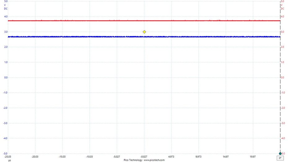
    3) I'm attaching a screenshot of the VBUS vs GND (BLUE probe) and VBAT vs GND (RED probe)
        In this screenshot, the USB is not plugged, the VBAT shows 3.75V and VBUS shows 2.65V.


    Here is a table of the values we read across PMIC pins:

    Those reading have been taken on 3 different boards with 3 different level of the battery.
    It also include reading when we encounter the Battery Overvoltage problem (which we think it might be related wit the 2.6V issue on the VBUS line)

    BOARD 5 5 5 6 6 6 8 8
    Pin ID No USB plugged
    No charging
    (V)

    USB plugged
    Charging
    (V)

    USB plugged
    Error
    (Battery overvoltage)
    (V)
    USB plugged
    No Error
    (V)
    No USB plugged
    No charging
    (V)
    USB plugged
    Error
    (Battery overvoltage)
    (V)
    No USB plugged
    No charging
    (V)

    USB plugged
    Error
    (Battery overvoltage)
    (V)

    VBUS 2.67 5.07 5.21 4.84 2.68 5.22 2.64 5.22
    PMID 3.86 5.07 5.21 4.79 3.49 5.22 3.5 5.22
    BTST 3.84 9.2 4.47 9.09 3.47 8.67 3.47 8.69
    SW 4.08 4.23 3.92 4.31 3.71 3.71 3.71 3.72
    VSYS 4.08 4.21 3.92 4.24 3.71 3.71 3.71 3.72
    BAT 4.09 4.2 3.95 4.2 3.71 3.71 3.71 3.71
    REGN 0 5.02 4.97 4.28 0 5.02 0 5.03

    Best regards,

    Matteo

  • Hello Matteo,

    Thank you for all of that testing information.

    Based on what these tests show I do not think that the bq24298 is the culprit for why voltage is present on the VBUS net when there is no USB connected. Let me unpack what I think that is.

    -The RBFET should be off based on the configuration you have and with its orientation the body diode is blocking the voltage. This seems to hold true that the RBFET is off because if it was on the voltage on VBUS and PMID should be the same.
    -The fact that the bias on VBUS is relatively consistent across all three boards when the voltage on the battery and the PMID is different.

    There are two ways that I think that we can test if there is another part of the system that is causing this biasing some how:
    -Independently disable the LDOs U3 and U4 while monitoring the voltage on VBUS to see if one of these supplies has coupled its output voltage to the VBUS Net.
    -If that does not give conclusive feedback for where the bias might be coming from one other test that would determine conclusively if the bq24298 is contributing to the bias would be to depopulate the bq24298 (U1) on one of these test boards and apply a test supply to the VSYS net to allow the rest of the system to power up and measure the voltage on VBUS when no USB source is present.

    Regarding the battery overvoltage issue is this determined by checking a flag in either the ba24298 or the bq27441? Are you using a somewhat standard Li-Ion battery with a nominal voltage of 3.7V and a full charge voltage of 4.2V? Looking at the results of Board 5 in the no USB case it seems like you are using a relative standard battery chemistry.

    Thanks for your responsiveness in providing the requested data to help solve this issue.