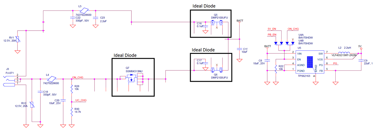
I have designed a TPS62163 5 V buck converter into a new product that I am currently testing. I have determined that plugging in a power cable consistently causes the chip to become damaged and stop functioning properly.
I just finished scoping the board to look for transients that would cause problems. The datasheet specifies that VIN is 20 V tolerant, EN and SW are tolerant to VIN + 0.3 V, and FB, PG, and VOS are 7 V tolerant. I've been plugging in a cable attached to a 7.4 V power supply (to simulate an average 2-cell battery voltage). Given that the input voltage is higher than the tolerances of the FB, PG, and VOS pins, I tried looking at those first, even though there is no connection between these pins and the supply other than through the buck converter itself. I scoped the VIN, EN, SW, and VOS pins on a unit with a damaged TPS62163, and saw no damaging transients down to a scale of 200 us/division. I then removed the TPS62163 completely and checked again, and still saw nothing that appeared to be able to damage the chip.
It seems that the next step would be to plug in the supply with a working TPS62163, but I do not like the idea of replacing the chip over and over again until I find the problem. Assuming that I do take this route, how can I minimize the number of devices I destroy while trying to identify the problem? Alternatively, what are some other troubleshooting steps I can look into that won't destroy more devices?
For reference, the power passes through a ferrite bead pi filter and two ideal diodes before reaching the buck converter, none of which seems to be likely to cause a problem like this.


