Other Parts Discussed in Thread: UCC27201
Hi Sir,
I use TI gate driver and MOSFET simulation DC Motor drive application power tool now.
I have two topology survey UCC27531 and UCC27201.
Since use Half Bridge driver motor, have MOSFET burn damage issue, I guess maybe MOSFET current rating not enough(just use one pcs).
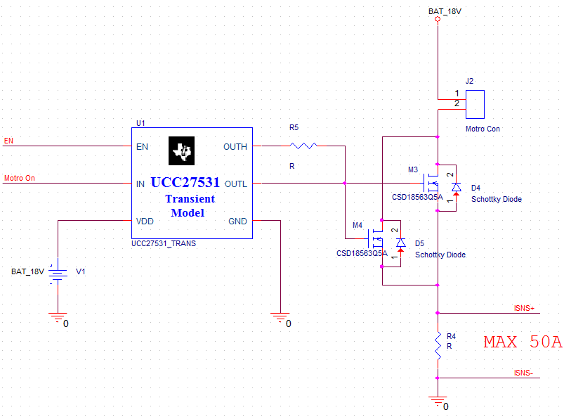
I think change to Low side driver motor and parallel MOSFET. Could you provide suggest comment for me? Thanks.
Half Bridge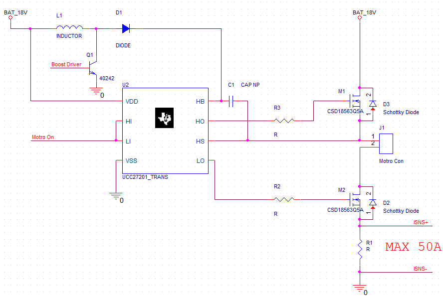
Low Side