This thread has been locked.

If you have a related question, please click the "Ask a related question" button in the top right corner. The newly created question will be automatically linked to this question.

TPS65217: TPS65217D power on failure

Part Number: TPS65217

Hello,

We have manufactured a number of boards using the TPS65217D PMIC and on the latest batch we are experiencing issues and it seems to be related to a specific "lot code" of TPS chip.

The power circuitry is based around the BeagleBoneBlack design which is very close to the reference design in the Ti datasheet.

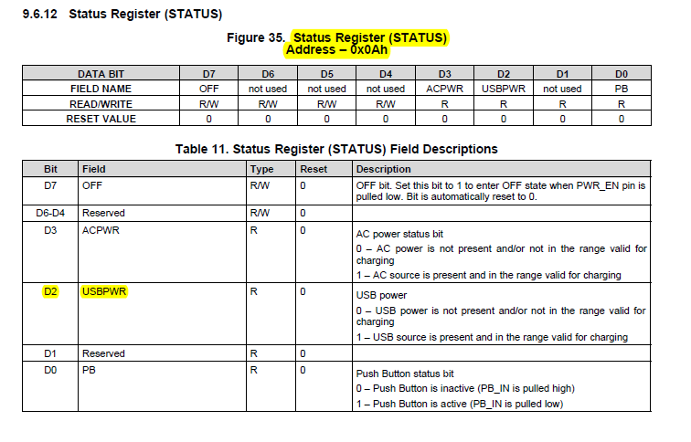
Our issue is when attempting to power on the TPS chip using the USB input the chip fails to wake up and bring up the power rails.  If we apply 5V to the AC input the TPS chip wakes up !

We have tried different combinations of powering the inputs in sequence or parallel and all the diagnostics are pointing towards the USB input, DC power is fine.

The DC power supply used to test both the AC and USB inputs and can supply well over the maximum capability of the TPS chip.

We can make the circuit power on from the USB input by applying a wire short between AC and USB!!

When we power on our boards using the good "lot code" of TPS chips they can be powered either by the USB or AC inputs independently without any issues.

We need to check to see if there are any known issues with certain "lot codes" of the TPS chip ?

Good "lot code" markings:

TPS

65217D

TI   611

CNYJ  G4

Faulty "lot code" markings:

TPS

65217D

TI   691

C4Z8  G4

Looks like same factory but different date of manufacturing.

Any help from Ti would be appreciated as we have over 250 boards with these controllers on.

Thanks

Marc

  • Hi Marc,

    Thanks for the post! We are taking a look at this. A couple questions for you to start off.

    1) Do you have a battery in this application?
    2) Also would you happen to have any screenshots of the USB power up for the two different lots?

    Let me know if you have any questions. Thanks!

    Regards,

    Paul Kundmueller
  • Hi Paul,

    Thanks for the response.  In answer to your questions:

    1) No there is no battery connected.

    2) Do you want scope traces of the lines or pictures of the setup ie cable connections to PSU ?

    Regards

    Marc

  • Hi Marc,

    Thanks for the quick response. For item 2), could you provide scope shots of the USB input voltage signal when the USB input is plugged in for the two different lots?

    In addition, I wanted to see if you could read the STATUS register (0x0Ah) in the scenario when you have shorted the AC input to the USB input. Would like to see if the device is detecting a USB source.

    Let me know if you have any questions. Thanks!

    Regards,

    Paul Kundmueller

  • Hi Paul

    We have grabbed some traces of the good batch and suspect batch.

    Good Batch:

    Suspect Batch:

    Both traces were taken using the same DC power supply and USB lead.

    The value of the i2c STATUS (0x0A) register for the suspect batch is 0x0C = D3 & D2 bits set.

    Kind Regards

    Marc

  • Hi Marc,

    Would you be able to share your schematic for the TPS65217D Only? I would like to have a more complete picture of the connections for TPS65217D. If so, I will send you a private message in order to securely share your schematics. Let me know what you think. Thanks!

    Regards,

    Paul Kundmueller

  • Hi Paul,

    No need for privacy, the project is open hardware and the schematics are hosted on github:

    Kind Regards

    Marc

  • Hi Marc,

    Thanks for the schematic! Are both the boards the same? Do both the boards have the same firmware? From the above screenshot it looks like something is current limiting the "suspect" lot. Is something different about that board in terms of more current draw from the SYS pin? Since it looks like TPS65217D is limiting the current could you take a scope shot for the "good" and "suspect" lot? The three signals that would be of interest would be the USB voltage, the USB current, and the SYS voltage. It would as be helpful to see how high the current is for the two lots. If you could measure how high the current goes on the scope that would be great.

    Also, a follow up question. Is this USB plug-in the initial power up event for the board?

    Let me know if there are any questions. Thanks!

    Regards,

    Paul Kundmueller
  • Hi Paul,

    We have been digging more into the issue and examining all the components on the boards had think we have found the issue.

    On the board there is an RGMII phy that is supposed to have a 4.7uH inductor connected so it can regulate its own power supply.

    We have found on the "suspect" boards the inductor seems to be incorrect/faulty.  Replacing the inductor with one from a known working board it powers up OK with no need for the connection between AC and USB.

    Thank you for your time and sorry for raising it as an issue.  We are now going to get onto the inductor supplier to find out how and why the incorrect part has been supplied.

    Kind Regards

    Marc

  • Hi Marc,

    Sounds like you found the root cause! Glad to hear. Let us know in the future if there is anything else you need help with. Thanks!

    Have a good weekend,

    Paul K