This thread has been locked.

If you have a related question, please click the "Ask a related question" button in the top right corner. The newly created question will be automatically linked to this question.

UC3843: Does switching noise matter in error amp, opto-coupler and UC3843 comp pin?

Part Number: UC3843
Other Parts Discussed in Thread: LM358

My isolated DC/DC design uses a LM358 as output error amplifier to an opto-coupler then to a UC3843 PWM.

The frequency compensation in the LM358 has low local phase margin so the resulting gain peaking amplifies the 300 kHz switching clock. The switching carrier is present all the way to the comp output pin on UC3843. 

Now the odd part; when the switching signal in the feedback circuitry is large everything is good. On samples where switching noise is reduced because LM358 sample has better phase margin, the whole DC/DC phase margin become bad. 

So my question is "does switching noise affect system phase margin"?

If it does affect it, how does it affect the system?

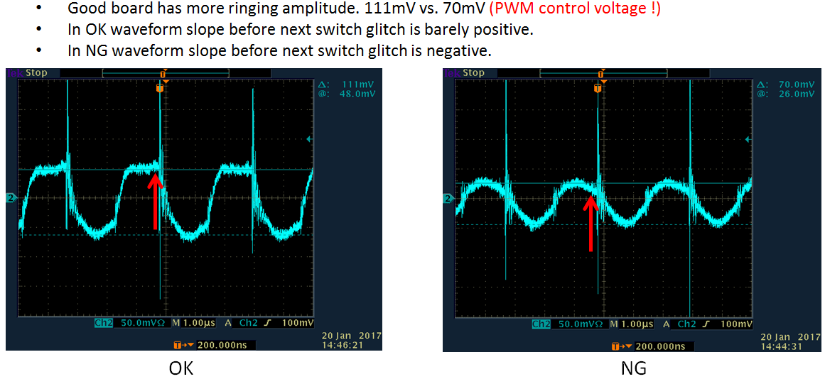
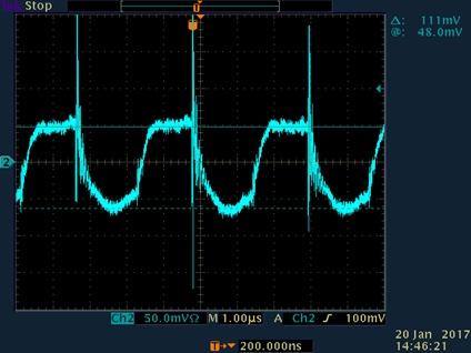
Here is UC3483 pin 1 on a good phase margin system.

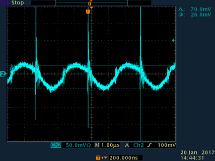
Here is UC3843 pin 1 on a low phase margin system.

  • Ron,

    Can you post a schematic so that we can see how the UC3843 and error amp are configured?

    In a typical isolated application, the UC3843 FB is tied to GND, which forces the COMP pin high. Since the COMP pin is the output of a transconductance amplifier, the feedback opto is then connected between the COMP pin and GND to pull current out of the pin, in order to regulate the COMP voltage level to achieve the required duty cycle for output voltage regulation.

    When you say that the LM358 compensation has "low local phase margin", what exactly do you mean? How are you measuring phase margin? How are you measuring the overall closed-loop phase margin of the power supply? When you say the whole phase margin becomes bad, how bad?


    How does the transient response look? This can also be used to infer loop stability and phase margin.

    Thanks,
    Bernard
  • Bernard,

    I am looking into this off forum now, but will post solution if one is found.
  • The problem is the ringing signal from the error amplifier on the VOUT side of the DC/DC convertor

    This ringing is present on the UC3843 comparator, the variable slope on the signal changes the bode results.