This thread has been locked.

If you have a related question, please click the "Ask a related question" button in the top right corner. The newly created question will be automatically linked to this question.

TPS62125: TPS62125 failure on a AC/DC converter

Part Number: TPS62125
Other Parts Discussed in Thread: TPS560200, PMP, CC2630, TPS62120, TPS62160

Hi,

I have PMP4447 based AC/DC converter that converts AC to 12 Vdc. And then, I am using TPS62125 as TI Webench suggested. Here is my schematics:

and the layout (TPS62125  is highlighted)

I have two issues with the TPS62125. I manufactured 100 pcs of this converter and I had almost 10-12% fail ratio. They were manufactured on a reflow oven by following standard reflow cycle (max 265 C for 5 sec). All failures were related to TPS62125 the modules worked fine after replacing the TPS62125. Somehow I also feel that it is too ESD sensitive. 

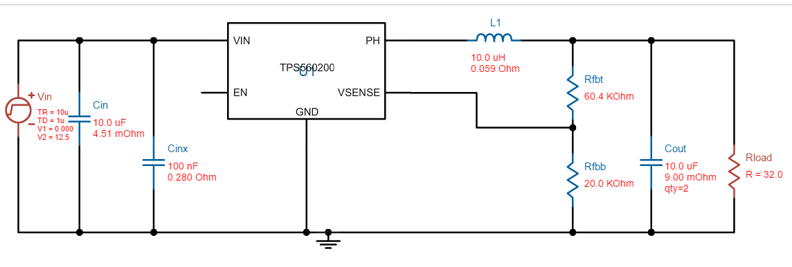
The second issue is that those 80 of those 100 modules are on the field and I had failure on about 5 of them. Those 5 had a failure on TPS62125  and worked fine after replacing them with a new TPS62125. I am not sure if it was a spike, ESD, or anything else caused the problem, but it looks like TPS62125  is too gentle to use it. I wonder if there is any visible issue with my schematics or layout? I am considering to replace TPS62125  with TPS560200.  Would you recommend TPS560200 as a replacement or another part?

The purpose of converting 3.2 V from 12V is to power CC26xx or CC13xx based RF chip. It is requires very low current. A consideration would be that it shouldn't cause disturbance to the RF chip.

Another question related to the above schematics. Would you recommend to use a TVS before the TPSxxx chip? I wonder if the 12V on PMP4447 may cause some spikes if there is any issue with the AC main. (it is an industrial application). I am using the same BOM list of the PMP 4447 including the Wurth Transformer.

I would appreciate your comments. Thank you.

750841034
  • Whichever way you go, you need to understand what is causing the TPS62125 to fail. Whatever is causing the failures could also cause the TPS560200 to fail. How do they fail? Do they draw high current, not produce an output voltage, etc.?

    The TPS560200 seems like it would be a larger solution, which does not seem like it would fit on your existing design. As well, it uses a different power save mode which typically has higher ripple--so, I am concerned about RF performance.

    Do you have a reason to believe that ESD is causing an issue? Are you using ESD-controlled handling during assembly? Does the customer have access to the PCB?

    If you don't use the EN comparator or PG functions, you can leave those resistors off of the PCB to save space. Your routing around the IC is difficult to read, but the output cap is for sure placed too far away and not grounded to PGND, where it needs to be.

    Could you send the part numbers for the inductor and input/output caps?
  • Hi Chris,

    Thank you for your comments.

    I am not really sure what is the issue. The main problem is that I have 12V output on the PSU but  I don't observe any signal output at the output of TPS62125.

     The below picture is from one module that was working when I test them at office, but failed on the field. It looks like I did a hand assembly 

    - As I experience from different cases, there should have been a physical damage on the case if there was an over voltage or current failure (none of the faulty modules have physical damage). CC2630 withdrawn very less current only about 7mA or less.

    - I have observed the PCB by a thermal camera, there is no heat issue. 

    - I visually inspected all the modules if there is any short circuit, and then did continuity test by a DMM before powering the modules. There was no issue.

    Do you guess any possible issue based on your experience what might be wrong? Would you suggest to place any protection circuit before TPS62125?

    I am attaching the gerber files if it would be easier for you to see the layout (I can share eagle cad file as well).

    Could it be layout related issue? One issue that maybe I should not have placed the inductor to the bottom layer to save space, instead keep them all on the same layer. What do you think?

    Regarding the components I use:

    C21, C22: 10uF, 25V, X6S, 10%, 0805: Part nr GRM21BC81E106KE11L  

    L21: 15uH, 750mA Par nmr: SRN4012T-150M 

    Regarding the ESD, the modules are produced in ESD-controlled environment, however, when we placed the modules into the enclosures, we didn't wear grounding straps and I noticed some of the modules broke after it. I assumed they broke because of the ESD issue (and due to very small package).  

    Thank you for the tip, I am not using the EN and PG pins. Then I can use like this, right?

    If you would recommend me to replace TPS62125 with another one, what would you suggest considering that it is for an RF device? If it is possible, I would prefer something like SOT package instead of WSON that is less likely to cause soldering related problem.

    Thank you very much

    PSU Module.rar

  • Especially since some units didn't work after you put them in your system (and they were working before), I think ESD or handling damage is a likely culprit. You should not be handling these ESD-sensitive devices without grounding.

    If you frequently see failures at the first power on, you should look at Vin, Vout, and SW as you apply power to your system. There may be some overvoltage.

    Similar devices with leads are TPS62120 and TPS62160. Your new schematic is fine.
  • Thank you Chris,

    If there is an over voltage issue, would you recommend to put a TVS or a larger capacitor? I have just had failure on two modules at the start-up of the PSU. It looks like it is getting damage at the start up.
  • You need to verify it is overvoltage by using a scope to see the voltage.

    Then, you need to understand why it is going OV. Adding a clamp circuit should be a last resort--you should try and fix the problem at the root cause, which is the OV event itself.