This thread has been locked.

If you have a related question, please click the "Ask a related question" button in the top right corner. The newly created question will be automatically linked to this question.

TPS54340: Spread spectrum clock design for TPS54340

Part Number: TPS54340
Other Parts Discussed in Thread: LM53635-Q1, TPS54160

Hi ,

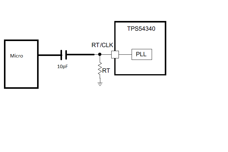
Im planning to use the TPS54340 buck converter in my design.For switching frequency,I wanted to use the spread spectrum based external clock generation using micro controller to avoid the EMI/EMC problem due to the power regulator.

I just drawn the schematic and can you pls let me know,this will solve my requirement.

  • Maybe the LM53635-q1 synchronous buck with integrated spread spectrum would be a better solution.

  • ...and your schematic and requirements are not attached.

  • Its not a completed schematic.Just the approach.

    My requirement is drive the Buck converter switching frequency from micro controller after micro controller turned ON.Before that,the buck converter should work on the RT configured value.

    I have attached the screen shot of my scheme.

  • You can definitely synchronize to an external clock. Several years ago I did some informal testing with a related device. I think it was TPS54160. I dithered the CLK with an FM modulated signal. I found that for delta F less than 5 kHz, the PLL remained phase and frequency locked. For delta F between about 5 kHz and 10 kHz, the SW node was frequency locked but not phase locked. Above delta F of 10 kHz, the PLL could not track the external clock at all. This was continuously variable FM modulation of the clock, no stepping or jumping of frequency.

    This is just by visually comparing the SW node and external clock traces on an oscilloscope. I'm sure there is dedicated test equipment that can give a more accurate measure of PLL capability, but I just used what I had available on my bench