This thread has been locked.

If you have a related question, please click the "Ask a related question" button in the top right corner. The newly created question will be automatically linked to this question.

UCC28700: Ucc28700 Waveforms on Oscilloscope

Part Number: UCC28700

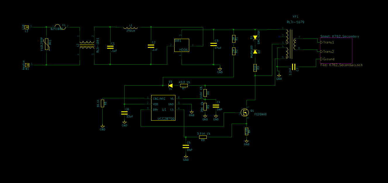
When trying to use the oscilloscope to view the waveforms, am I supposed to ground the oscilloscope probes? I do not have an AC power supply. I am using Mains Voltage 120VAC 60HZ. When I tried grounding the probe, the probe blew up. Why is this and how can this be fixed? Will using an AC power supply help? I have one ordered and on the way now.

  • Hagen

    You need to do one of the following:

    - Isolate your AC mains supply through an isolation transformer

    - Use an electronic AC or DC source with an isolated output

    - Use isolated or differential scope probes.

    - Power your scope through an isolation transformer


    The problem you are having is a common problem when probing AC power supplies. Even seasoned experts can get caught out by this sometimes.

    The issue is that for the non-isolated AC mains supply, the Neutral and Earth sit at the same potential, they are usually bonded together somewhere back along the AC distribution network, at a sub-station. But the "ground" clip of your standard scope probe is connected to the chassis of the scope, which is also connected to Earth through the AC power cord of the scope.

    So when you connect the ground of the scope probe to the DC- of the bulk cap, or any point after the diode bridge, you end up shorting out one side of the bridge rectifier - one end tied to Earth (through the scope ground), the other end tied to Neutral (which is at Earth potential). This causes a huge current to flow, typically blowing the input fuse, diode bridge and probably any surge/inrush resistor if used.

    By using an isolation transformer to power the AC supply to either the scope or UUT, you can avoid this short, and can then probe the circuit using regular scope probes.

    If you don't have an AC mains freq isolation transformer, or an isolated AC or DC source, you will need to use differential probes - but be sure to NOT connect the Earth/ground clip of the diff probe, just leave it floating.


    I hope this helps to answer your question - if so, please click the "verify answer" button.


    Thanks,
    Bernard
  • Bernard, thanks for the quick response. I will try your suggestion!
  •   While I wait for my AC power source, I am trying to use differential probes to measure the waveforms. I have realized that I am only getting about 15 VDC on the VDD pin. Therefore the chip never reaches turn on voltage. I have seen this circuit work before and I am wondering what could be causing the low voltage now. I

  • Hagan,

    After the board was damaged, what components had to be replaced? It's worth checking if there are other damaged parts, in particular the UCC28700 IC, and the startup resistors R1, R2.

    Maybe it would be better to start testing on a fresh board?


    If you have a DC source available that can go to 100 V or so, you can test with that for now.

    When input voltage is applied (AC or DC), what voltage is at the top of C3?

    Can you see the VDD pin rising exponentially from 0 V towards the 21-V start level?

    The training & debug guide for the UCC287xx family might be useful for you:
    training.ti.com/getting-started-ucc287xx-family


    Thanks,
    Bernard
  • There are all new components on the board. I do not have a DC power source available. My DC power source recently broke. I have 170VDC at the top of C3. I was seeing the voltage rise (slowly) from 0 to 21 on the vdd pin and once it got to 21V it started jumping around. However, now it it is just jumping around 15V and never reaching 21V. I have been watching the training video and will try to continue looking at waveforms once my AC power source comes in the mail.