This thread has been locked.

If you have a related question, please click the "Ask a related question" button in the top right corner. The newly created question will be automatically linked to this question.

TPS92515HV: Analog dimming issues

Part Number: TPS92515HV
Other Parts Discussed in Thread: TPS92515

Hello,

I have some troubles using analog dimming with TPS92515HV.

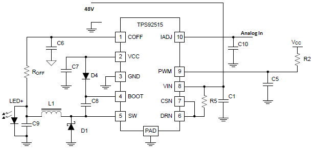
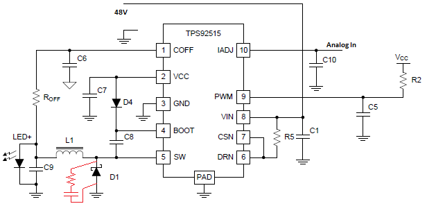
I use datasheet schematic:

Where I use:

Vin=48V

LED is 12V 1A (used with 550mA)

C6=470pF

D4=MMSD4148T1G (100V, 200mA)

D1= Schottky SS2FH10

R5=0,37ohm (to have 550mA on LED)

PWM tied to Vcc

Iadj used with analog input (0-2,5V)

the problem is that at minimum light (Iadj=0) I'm not able to set low current on LED. On datasheet is reported that analog dimming ratio should be 200:1, I make lot of test but lower current that I can see is 9mA (about 50:1 because maximum current on LED is 550mA)

I try a lot of configurations, here I report some results:
L1=100uH and Roff=27kohm --> LED current is 26-550mA, Fsw=540-633kHz
L1=100uH and Roff=47kohm --> LED current is 18-550mA, Fsw=312-374kHz
L1=47uH   and Roff=25kohm --> LED current is 41-490mA, Fsw=664kHz
L1=270uH and Roff=57kohm --> LED current is 9-560mA (don't remeber Fsw, I think about 370kHz)

Best result is using big L1 but I have no space to use L1>100uH (maybe i can find 120 or 150uH).

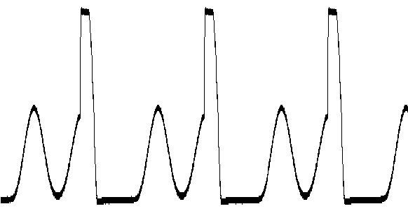
Another problem is that when I have a small current I have a bad waveform on inductor input: I can see sinewave before pulse. I can reduce sine wave incrementing Roff but minimum current on LED increases (because is increasing also Fsw).

Here is a picture of waveform that I can find on inductor using L1=270uH and Roff=57kohm:

Do you have some suggestion to improve analog dimming?

thank you a lot

  • Seems that analog dimming behaviour improves using lower switching frequencies, but the sine wave on inductor increases its effect...

    I have new resultst using L1=100uH and Roff=94kohm.

    this is Voltage on inductor:

    Adding RC filter in parallel using 3k9 resistor and 100nF capacitor it improves, this is the result:

    I can reduce amplitude of sine wave but i have 10Vdc that should not to be... who is that introduces this phenomenon? In what way I can eliminate it? (Voltage on Coff is a clean sawtooth wave)

  • Hello,

    Analog dimming can have its limits under certain conditions. The off time is set so the on time will vary to vary the duty cycle. In the case of analog dimming the on time will reduce as the current is reduced. It will continue to do so until the minimum on time is reached at which point you cannot dim further. This is why using a lower switching frequency helps, it allows the minimum effective duty cycle to be lower so you can dim further. You can test this by reducing your input voltage to 24V and you will see that you can dim further.

    As for the sine wave and the switch node settling to 10V that is normal operation. When you operate in discontinuous conduction mode (inductor current falls to zero) that will happen in any inductor based switching regulator. When current falls to zero it will ring due to the output capacitor and parasitics until the switch node settles to the output voltage.

    Regards,

    Clint

  • Thank you Clint,

    I understood your explanation... (I haven't experience with switching regulators)

    I noticed that on time could not be smaller than 200ns (on my configuration).

    Now I also understand that Sine wave that I can see on switch node is not a problem (Yesterday I was thinking that it was charging inductor, but it's wrong. It's simply output voltage that is "coming back", is it correct?)

    So, today I increase Roff to increase period.

    I find new values for Roff (180kohm) and for R5 (0.09ohm), I add RC filter on D1 (using 3k9 and 100nF) and I reach 110:1 dimming ratio! :-)

    Do you think that Roff and R5 values that I use are ok? (or there are some pratical limits that is better do not cross)?

    here some pictures of new results:

    RC filter (in red):

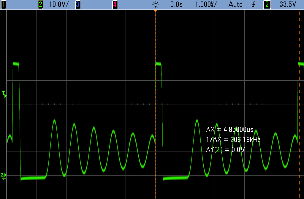
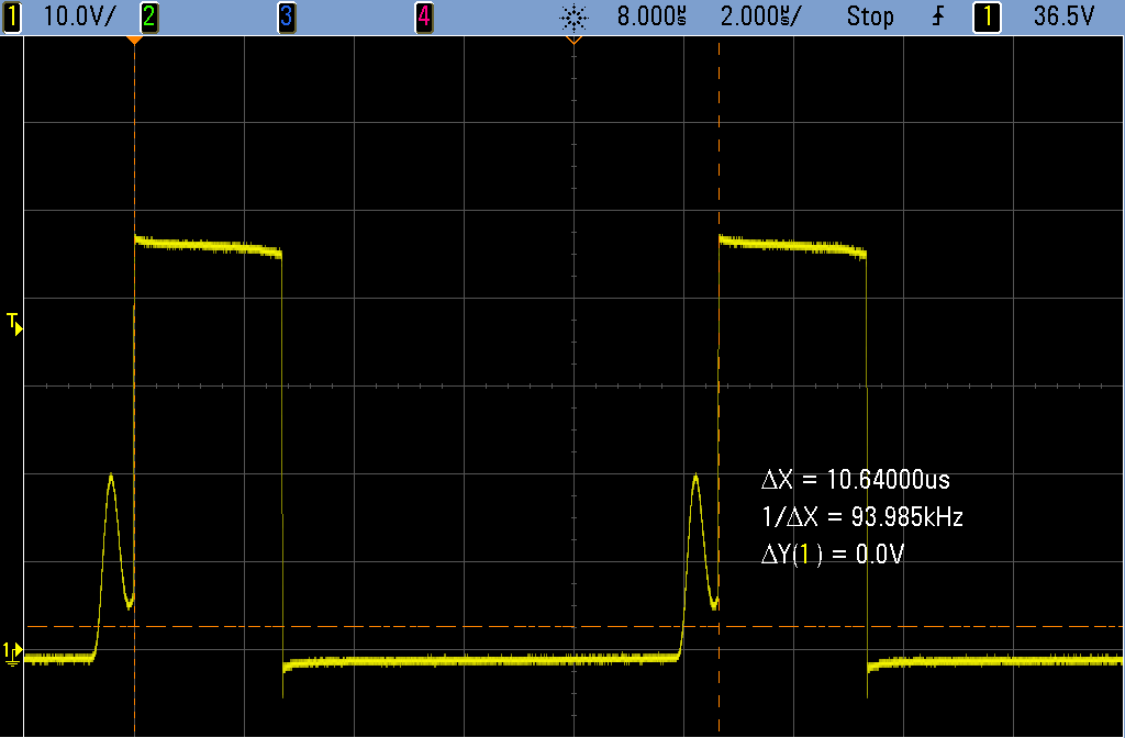
    Voltage of switch node using Max dimming:

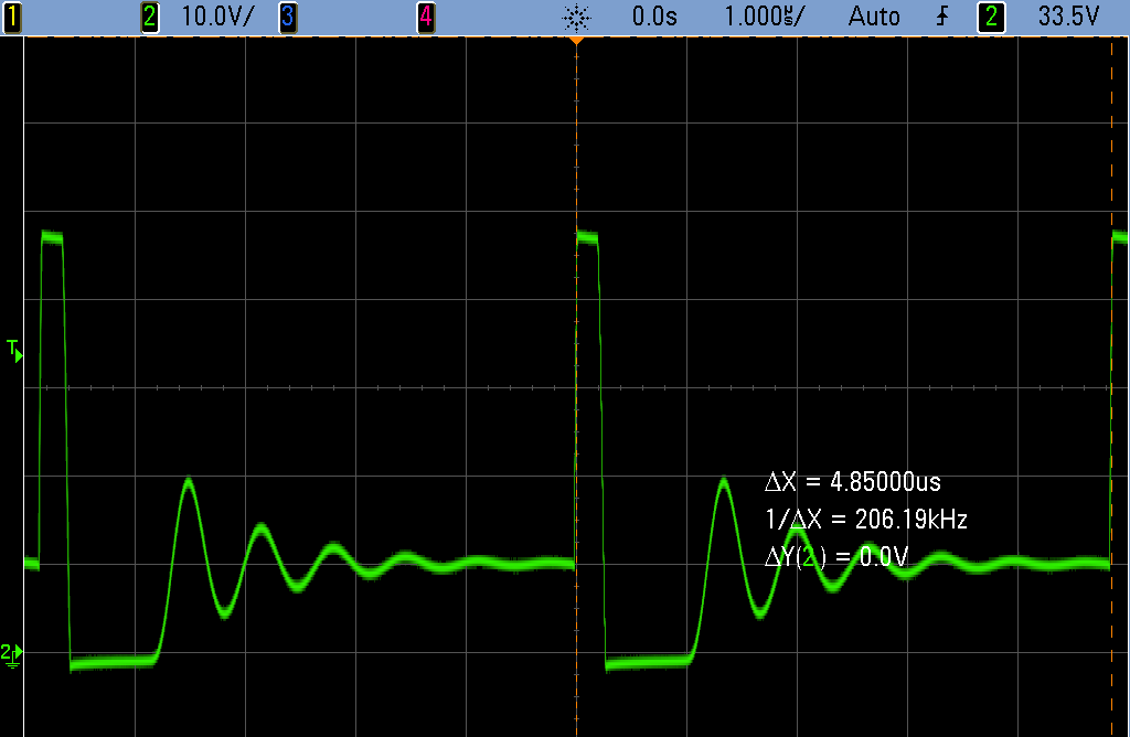
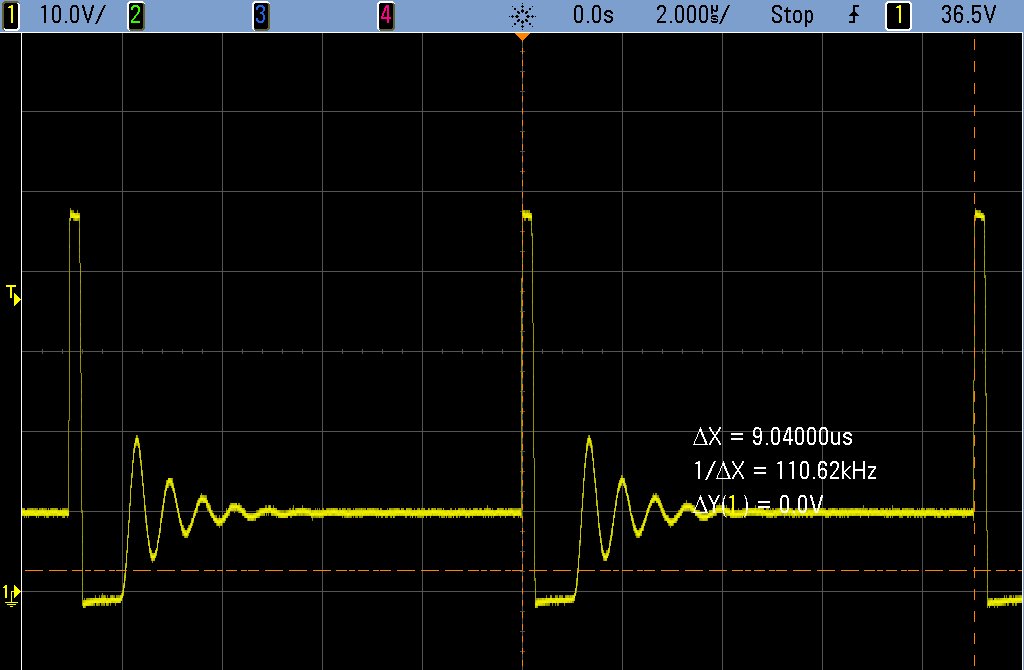
    Voltage of switch node using min dimming:

    Thank you and regads!

  • Hello,

    Those values are fine and what you are seeing is right about at spec. The minimum on time specified in the electrical characteristics is 195ns typical. I am happy you have seen improvement. If you don't mind my asking could you tell me what type of application this is for that requires a wide dimming range? I understand if not, I am just curious and like to know how our devices are being used.

    Thanks,

    Clint

  • Hello Clint,

    The board that I'm developing is for a 5W LED spotlight, for consumer lighting. One requirement is to have a wide range dimming. Sorry but I can't write here all details...

    Best regards and thank you so much for your support!
  • Hello,

    I have a new problem with this board (schematic is on above post of feb 7).

    I can't turn off LED using Iadj pin: if it is driven to 0V LED is ON with a minimum current.

    I tryed to increase Roff I can't turn off LED (also if I remove Roff LED is ON!)

    I can't find the cause of this issue, do you have any suggestions?

    Thank you a lot

  • Hello,

    The TPS92515 has a maximum off time and a minimum on time, so even at IADJ of 0V there will be some small amount of LED current. The only way to make it zero is to pull the PWM pin low. Most LED drivers operate this way with analog dimming because otherwise some parts would have zero LED current and some would still have some LED current depending on the direction of the error amp offset voltage.

    Regards,

    Clint