This thread has been locked.

If you have a related question, please click the "Ask a related question" button in the top right corner. The newly created question will be automatically linked to this question.

TINA/Spice/LM1086: my schematics might be wrong. Libraries for Eagle/Altium?

Part Number: LM1086
Other Parts Discussed in Thread: TINA-TI,

Tool/software: TINA-TI or Spice Models

Hello, I have two questions please regarding this component.

1) Can I find somewhere the lib for the LM1086 for Eagle/Altium? It seems I need to make my own because it's missing from my libraries and I am not experience with that. 

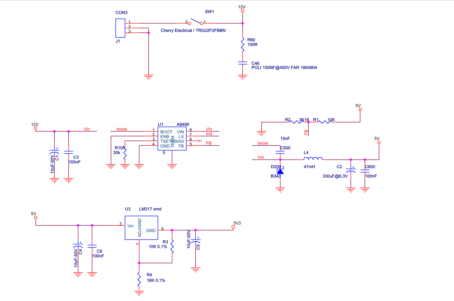
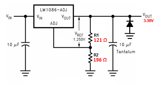
2) I am afraid that my schematics (designed by someone else) are wrong.  Please see the following, the regulator is replaced by LM1086, R3 =120 Ohms and R4 = 200 Ohms. The Vin=5V, Vout =3.3 V, Vadj =2 V. It seems that when I plug my power supply on a laptop I see a huge spike in the output ( from -10V to 10V) I believe that this might have destroyed some pcbs. I also see spikes on the outputs of two cameras. As a result, usually one of the cameras is not recognized anymore. Isn't the role of the voltage regulator to provide 3.3 V stable  and robust to external disturbances? Could it be that the Rload in the output the designer selected is wrong? Maybe I should replace it with a bigger value and the capacitor at the output as well? How should I choose the cap?

Please make any suggestions if you re more experienced in that. All the components on the pcb are smd. It is hard to measure the cap without removing it and I am afraid I won't re-solder it correctly. Thank you in advance !!!

  • The LM1086 CAD symbols are here:

    www.ti.com/.../quality

     "( ... from -10V to 10V) ... "

    If you are saying the LM1086 output voltage is starting at -10V, rather than 3.3V, then something is not correct.

    This should not happen, not even as a start-up transition. Since there are only positive voltages in this circuit, the source of any negative voltage needs to be understood.

    I would suggest adding a diode to the LM1086 output to clamp the negative transition.

  • Thank you so much for your reply. I simulated the response in LT-Spice. Correctly, I dont get negative values. But in reality I do still receive them, both at the input and output when I plug in my power supply abruptly. Would you recommend a bigger Rload or more diodes, as this article proposes? www.digikey.ch/.../protecting-inputs-in-digital-electronics

    In case I have a bad connection, I will try again on the breadboard, because the pcb is a bit tricky.

  • If you indeed have 'long wire' then the in-rush current needed to charge the assorted capacitors through the wire inductance ~might~ be the root cause of the +/- voltage transient.

    Adding clamping diodes probably will not fix the voltage transients, but it should limit them, and that's a start.

    Without knowing the real source of the transient it's difficult to know what a proper fix might be.