This thread has been locked.

If you have a related question, please click the "Ask a related question" button in the top right corner. The newly created question will be automatically linked to this question.

TPS54020: Large Input and output ripple with barely any EVM modifications

Part Number: TPS54020

Hi team,

My customer is trying to quickly design in the TPS54020. Their Vin = 10V and Vout = 5V. The fb Rdivider was changed to 1.5k and 11k to achieve the 5Vout. They also removed the EN pullup resistor and are providing their own EN signal. Other than that, no modifications were made. They are using the PVIN path for their input.

They are seeing larger than 1V input and output ripple, Here is the Vout:

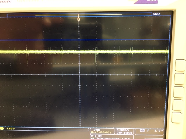
I recommended increasing the inductor larger to reduce the ripple current, but I am wondering why the Vin ripple is also large? Any other recommendations? 

  • That is not "ripple" but rather "switching noise". You have to be careful when measuring it. Measure directly across the output capacitor with very short (< 1 cm) GND lead, or better yet use "tip and barrel" method. If the observed switching noise is still too large you can consider some additional HF bypass on the output, 0.1uF, 0.01uF, 0.001uF. Or possibly add an RC snubber from PH to GND close to the IC.

    Vin ripple may be large, depending on output current. If it is just switching noise, the above may help the input as well. If it is true ripple then increase the input capacitance.
  • Yes, I agree it is switching noise and the noise is similar whether or not there is load. Also, the input voltage is supplied from another much larger power switcher but the voltage is very quiet when the TPS54020 is not enabled. In both cases, the measuring technique is same. I will add 10nF on the output to see if I can remove those high F switching noise.

    Do you still believe I should increase the inductance to 4.7uH?
  • Is there a relation between Input voltage and switching noise? I am supplying 5.5V and output is noisy as you can see in the scope shot. When I increased it to 6V, it is much quieter!
  • I am not sure if I my previous message got through, but I notice that the switching transients increases an the VIN goes closer to 5.5V for 5V output. Is this expected? Do I need to increase the frequency for lower input voltages? What is the minimum input voltage can I supply for 5V output?
  • Drew,

    According to the datasheet equation, if you left the switching frequency at 500kHz and your inductor was 4.7uH, your K-ind would be a bit over .1, which his within the recommended range .1-.3. (meaning your ripple current is within 10%-30% of your max Iout).

    Conversely, leaving the inductor at 1.1uH would put you at ~25%, which is also within the healthy range. If you left it at 1.1uH you would get a bit faster of a transient response, and since we decided your problem here is not ripple, increasing the inductance is not necessary.

    Whatever you decide, remember that Cout needs to be individually calculated as well to ensure stability. See section 9.2.2.3 in the datasheet.

    Thanks,

    Brian A

  • Got it.

    I see an issue with the way I was measuring, if I put my ground at PGND then the transients are much lower ~200mV. In addition, if I increase the input voltage to 6V, the transients are less frequent and lower in amplitude as well.