This thread has been locked.

If you have a related question, please click the "Ask a related question" button in the top right corner. The newly created question will be automatically linked to this question.

BQ24296: BQ24296 is overcharging cells

Part Number: BQ24296
Other Parts Discussed in Thread: CSD17483F4

Dear all,

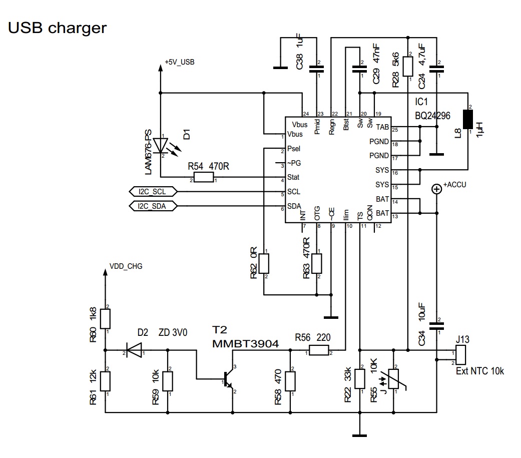
I have a really strange problem with BQ24296 charger. It is used as charger only and charging currents required are up to 2 A. I can externally adjust charging current (regarding to undervoltage treshold) using additional transistor on Ilim, which works (I can switch between high/low charging current), but I have a very strange problem:

cell is charging also, when top voltage is reached or when module is in error mode (LED is blinking; i.e. I disconnect NTC). Actually, when the cell is empty, charging works ok. CC phase is finished, module goes to CV phase and also holds voltage at 4,207 V, but when the cell is full, charging still continues (current around 230 mA, LED goes off) as charger would go back to CC mode (without CV limit). The same happens, if I disconnect NTC and put module into error mode: "normal" charging is terminated and charging current goes to (around) 230 mA.

So, speaking simply, charger is charging the battery also when in error or overvoltage condition. How this can occur and how to avoid it?

Best regards,

Gregor

p.s. Test has been done without T2 as well, no changes. I2C is disconnected and nothing has been sent to chip.

  • hello Gregor,

    I can't see big mistakes on the schematic, just few notes:

    a) is the system tested stand-alone? how do you measure battery current and voltage? What is the input source (lab supply, usb, …)?
    b) I can't see output cap bank for the buck (on SYS)? be sure you have at least 10 or 22uF...
    c) be sure R22 and R28 are 1% or that the voltage on TS pin is correct (use a potentiometer in place of the NTC if you want to perform tests on thermal protection)
    d) increase C38 (10uF)
    e) you can replace the whole block R60 + R61 + D2 + R59 + T2 with a single CSD17483F4 (or similar) and drive it directly from a GPIO (you will save money and space on the board)

    KR
    Vincenzo
  • Dear Vincezno, 

    thanks for your answer. You were correct that capacitor on SYS was missing and this caused behaviour described.

    We will also implement other features that you suggested!

    About circuit around T2 it cannot be replaced, because this is a circuit designed to lower charging current when some (low) voltage treshold on input occurs. But thanks for suggestion!

    Many thanks and best regards,

    Gregor