This thread has been locked.

If you have a related question, please click the "Ask a related question" button in the top right corner. The newly created question will be automatically linked to this question.

LM3150: Current Limit Not Tripping

Part Number: LM3150

Hello,

I am working with the LM3150 using the BSC059N04LS as my low side MOSFET. I have not been able to get the current limit to trip even when both my calculations and scope captures suggest that it should be tripping and as a result skipping cycles to try and recover.

Input Current

.2A

Input Wattage (I * 27V)

5.4W

@85% efficiency, Output Wattage

4.6W

Output current (output W/4.3V)

1A

Resistor (ILIM)

43 Ohm

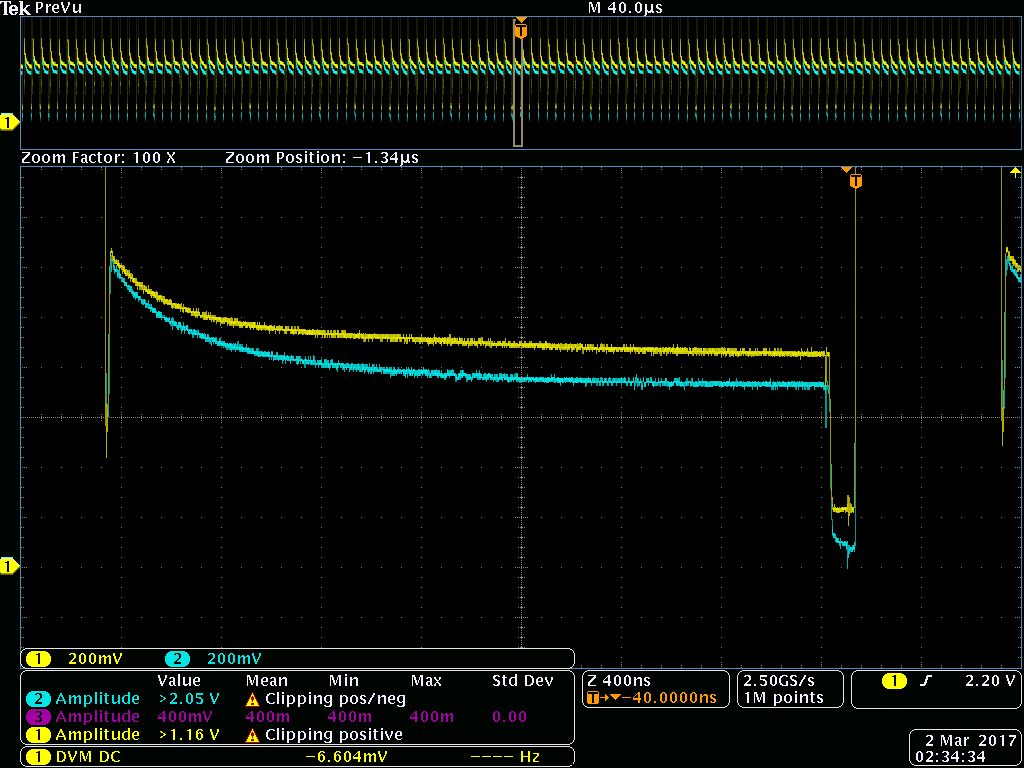
Here is a capture of the ILIM pin voltage (CH2) and the voltage across the low side FET (CH1). The FET voltage is clearly higher than the ILIM set voltage but the next cycle is not skipped.

I am running out of ideas for why this part is not operating the way it seems like it should.

Note: There is a Feed-forward capacitor, Ripple Injection Network across the inductor to FB, and a snubber in this set up. Have any of these additional circuits shown to interfere with the current limit functionality?

  • Ryan,

    My feeling is that you should be measuring voltage across RILIM (between ILIM and SW pins) not ILIM pin voltage - or am I just getting the datasheet wrong?

    Piotr
  • Hello Piotr,

    The measurement of the voltage across RILIM can be determined by taking the difference of the voltage on the SW Node and the ILIM pins. In this case it seems to have a more steady state value of 80mV.

    Looking at the internal block diagram unless there is a internal reference voltage that is used on the positive comparator pin the voltage at ILIM would have to be negative to trip the current limit.

    Do you have an example of the current limit working that you can post here?
  • Hello Ryan,
    Let me try to explain how this current limit works.

    First thing is the current limit is valley current, meaning the bottom of the triangular shaped inpuctor current. It make the decision to skip a cycle if the current exceeds the threshold just prior to the subsequent ON-time. Keep in mind the inductor current causes the SW node to be negative during the OFF-time. There is not a reference voltage on the current limit comparator but a reference current of 85uA that leaves the ILIM pin. This current flows through the ILIM resistor during the OFF-time while the bottom FET is conducting. In all cases the SW node is negative through the complete OFF-time. The reference current through the ILIM resistor creates a positive drop referenced to SW node. If at the end of the OFF-time, the ILIM input voltage is still negative then the comparator will trip and skip a cycle. It would be the over current condition for this to occur. The worst case RDSon of the FET is 0.0059 ohms. Using equation (6) on page 11 of the data sheet you will need to calculate the ripple current based on the inductor value and ON-time chosen. I don't have these values from you design. But the value of 43 ohms for your ILIM resistor value seems far too low. Check the decimal placed on the ILIM value and you will get a better result.
  • Hello Alan,

    Thank you for chiming into my question.

    I will work on getting the rest of the design information but the reason for the 43ohm ILIM resistor is to try and force the LM3150 into current limiting and it is not. The preferred ILIM resistor value for this design ~1kohm but since we could not get the limit to trip in extreme cases even when the current limit should have been exceeded we are testing down in the range of ILIM that it should be tripping during normal operation and we have not been able to achieve that.
  • I clearly missed the point of the 43 ohm resistor value...that even with such a low value it would not trip OCL.

    Sorry for that. I would then suggest two other things.

    A) RDSon of the bottom MOSFET needs to be high enough that a detectable voltage can cause current limit to occur at the intended current limit level.

    - This means the best MOSFETs with low RDSon values may cause current limit detection issues.

    The data sheet EC table states that the ILim current though the external resistor as 75 to 95uA across temperature. This variance need to be taken into account.

    B) I think the layout of the PCB can be an issue because the voltage detection for current limit is not measured differentially across the bottom MOSFET terminals; Instead it is measured relative to the ground pin of the LM3150.

    -This may mean the PGND & SGND ground nets of the LM3150 needs be wired with a wide discrete trace to the source pins of the lower MOSFET. This will reduce errors in voltage sensing for the current limit function.I hope to creat a new EVM layout to show this but I expect that layout not to get started until next month.

  • Hello Alan,

    Thank you for your reply. Your comments about the noise on the the Low-Side FET differential voltage measurement and the variation on the ILIM bias current makes a great deal of sense.

    When it comes to increasing the Rdson or any measure that increases losses or cost to achieve a larger signal voltage those are absolutely only as a last ditch effort.

    Are there any ideas if Snubbers, Feed-forward capacitors, or ripple injection circuits could be contributing? I ask because the Rdson and bias current being the reason why the LM3150 does not trip when the current is >3x the current limit.

    Do you have a preliminary App Note for the adjusted EVM layout that I could use ahead of the publication of the update EVM collateral?