This thread has been locked.

If you have a related question, please click the "Ask a related question" button in the top right corner. The newly created question will be automatically linked to this question.

BQ25505 energy harvester for Plant Microbial Fuel Cells.

Part Number: BQ25505
Other Parts Discussed in Thread: BQ25504, BQ25570

Hi,

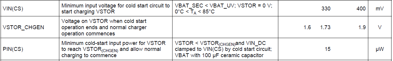
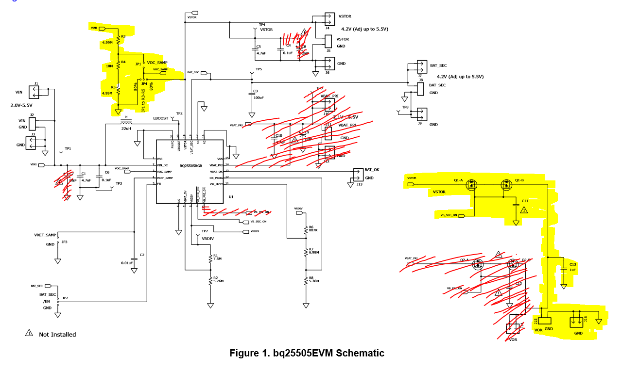
I'm trying to design a boost convert/charger for DC-DC low voltage system. My energy harvester is a Plant Microbial Fuel Cell and I'm trying to design a boost converter/charger that can increase the input current from microWatts to milliWatts. I'm not really sure if bq25505 is the correct IC for me to use. The Plant Microbial Fuel Cell produces 50mV - 200mV with a current of 50uA - 200uA given the external load is 1000 ohms. I want to boost the power output to supply a load. I'm still deciding on what load will be suitable. I'm deciding between a mobile phone battery or a set of LEDs connected in series.

I'll really appreciate it if I can get some help figuring all this out. I'm only a student and this is my first time in designing something like this and I'll need all the help I can get.

Thanks you.

  • Hi Haunya,

    Are you only using one MFC?

    The energy harvesters in our portfolio require typically 330mV for the Cold Start circuitry to begin. Based off the voltage range you specified, the Microbial Fuel Cell (MFC) output won't be enough for the Energy Harvester to begin charging.

    Cold Start charges up the VSTOR voltage. Once VSTOR reaches a certain voltage (1.73V typical), the IC enters a normal charging operation mode.

    Once in normal charging mode the harvester can boost input voltages as low as 100mV. Anything below 100mV may work but is not specified by our datasheet and cannot be guaranteed.

    For more information on Cold Start refer to section 7.4.2 starting on page 14 of the BQ25505 datasheet.

    -Joe

  • Hi Joe,

    Thank you so much for clarifying that and I also agree that I have to increase the number of my Plant Microbial Fuel Cell. Currently I only have two PMFC's setup and from the two I can only harvest  approximately 100-200mV.

    Therefore, with that being said, if I increase the number of my PMFC's and the combined output voltage is approximately 300-500mV or 300-400mV, will that be sufficient enough for the IC to operate on Cold Start and continue operating??

    Is the input voltage the only parameter that I should be concerned with to get the IC working or does the input power and current important as well?

    Thanks.

    Haunya

  • Haunya,

    I will answer your second question first.

    Haunya Hwanawi said:

    Is the input voltage the only parameter that I should be concerned with to get the IC working or does the input power and current important as well?

    You need to consider input voltage (VIN) and input power (PIN). PIN needs to be 15uW or greater for VSTOR to reach ~1.73V to begin normal charging operation. These are specified in the Electrical Characteristics table. I have also pasted them here:

    Haunya Hwanawi said:

    Therefore, with that being said, if I increase the number of my PMFC's and the combined output voltage is approximately 300-500mV or 300-400mV, will that be sufficient enough for the IC to operate on Cold Start and continue operating??

    If you increase your output voltage to be within the VIN(CS) spec, and have sufficient input power, then yes it should be enough for Cold Start. I recommend designing to reach the MAX VIN(CS) spec to be safe. 
    Once Cold Start ends and normal charging commences, the input voltage can go as low as 100mV. So, it may take some time for all the PMFC's to output enough Voltage/Power, but once they do the IC should continue boosting for lower input voltages.
    Also, the BQ25505 is designed to charge a secondary battery (VBAT_SEC), while allowing connection to a primary battery (MUX between the two). This may be an unneeded feature for your design. If so, I would refer you to the BQ25504.
    Regards,
    Joe
  • Hi Joe,

    Thank you!
    Since you've mentioned the secondary and primary battery I have a question regarding that. Is it a must to always connect a secondary and primary battery to the boost converter or I can omit that. Because at the moment, I'm trying to design a boost converter to supply power to light a single LED or a few LED's in series. 
    If I decide to use a super capacitor will that be connected to the VBAT_SEC pin of the IC?
    I really appreciate your help. It's my first time designing something so my questions might be basic.
    Thank you once again.
    Also, what's the main difference between the bq25504 and bq25505?? 
    For the type of load I'm trying to supply power to what would be a better option, bq25505 or bq25504?
    Kind Regards,
    Haunya
  • Haunya,

    I am glad you came to TI for help! The datasheets are very detailed and the answers to these questions can be found there. I advise carefully reading the datasheets.

    In the mean time, here are the answers to your questions:

    Haunya Hwanawi said:
    Is it a must to always connect a secondary and primary battery to the boost converter or I can omit that?

    It is not a must.
    Haunya Hwanawi said:
    If I decide to use a super capacitor will that be connected to the VBAT_SEC pin of the IC?
    Yes.
    Haunya Hwanawi said:
    Also, what's the main difference between the bq25504 and bq25505?? 
    bq25505 has the ability to MUX between the VBAT_SEC pin (the rechargable battery/super cap) and the VBAT_PRI pin ( i.e.  an additional non-rechargeable battery for back up).
    bq25504 does not have VBAT_PRI option.
    If you are interested, there is also the bq25570 which is essentially the same as the bq25504 but with a buck included for an additional regulated voltage rail.
    Haunya Hwanawi said:
    For the type of load I'm trying to supply power to what would be a better option, bq25505 or bq25504?
    I would recommend the bq25504, but I would suggest adding a super cap to your design and attaching to VBAT.
    Please hit "Verify Answer" if your questions were answered.
    -Joe
  • Thank you! I really appreciate the help.

    -Haunya
  • Hi Joe,

    From our previous discussion, I've decided to go ahead and use the bq25505 as the IC for my boost converter. Therefore, I'm using the bq25505EVM schematic as a guide for my design. Below is the schematic of the EVM. I've crossed out the components/parts which I don't need in 'red'. However, the highlighted parts in 'yellow' are the ones that I'm not too sure if I need or don't need. Are they important to the functionality of the boost converter or can they be omitted?? Can you please help me point out parts on the schematic that are not necessary to use and can be removed. I'd really appreciate all the help I can get. 

    Thanks.

    - Haunya

  • Haunya,

    Since you are not intending to use a primary battery there is not need for an option to select one or the other, so the highlighted circuit in the bottom right can be omitted.

    The highlighted circuit in the top left is useful for the EVM because it allows for users to easily switch the voltage seen by VOC_SAMP, which in turn regulates VIN through MPPT. You can omit this part of the design but need to set your VOC_SAMP pin.

    Follow the guidelines below and in section 7.3.1 of the BQ25505 datasheet.

    tie VOC_SAMP to VSTOR to sample at 80% of input soure open circuit voltage.

    Or you can connect to GND for 50%.

    If you want a percentage somewhere in-between, then connect to the mid-point of external resistor divider between VIN_DC and GND.

    Regards,

    Joe

  • Thank you!

    Cheers,

    Haunya
  • Hi Joe,

    I designed my circuit using the bq25505 and I'm worried that the resistor in series with my LED is going to take up too much power and that the LED might not be bright as I want it to be not worse might not come on at all. Therefore,  is there a LED driver from TI that can be incorporated into my design? Can you have a look at my design and if you're able to help what would be a good suggestion?

    Thanks.

    Haunya

  • Haunya,

    I don't think you will need an LED driver.

    You need to look at the LED datasheet. Pay attention to Forward Voltage and Forward Current. As long as you are providing a voltage higher than the forward voltage, your LED will turn on. Its brightness is then determined by how much current you are providing. Your series resistor will limit the current and therefore the brightness.

    If you are concerned the resistor is taking too much power, reduce your resistance. You can also look into a different LED with lower forward current required for different brightness. Look for forward current vs. brightness plots in the datasheet.

    -Joe
  • Hi Joe,

    Thank you so much! That makes a lot more sense. I'll probably remove the resistor or choose a LED with a lower forward current. 

    I also wanted to ask about the Cold Start feature of the bq25505. I have a big concern that the Plant-Microbial Fuel cells (PMFCs) I have set up will not be able to provide the required voltage and power the IC requires to enter Cold Start. Therefore, I'm really running out of options on what to do and I'm kind of stuck. However, I think I read somewhere on the datasheet that if I don't want the IC to enter Cold Start and to start charging/ supplying power to the load right away, can I connect a partially charged super-capacitor onto my circuit??

    Will that help in terms of the IC not necessarily needing 330mV - 400mV and I can get away with my PMFCs only supplying say 180mV - 200mV?? As long as I have a partially charged super-capacitor connected to VBAT_SEC??

    And if I do have a partially charged super-capacitor connected to VBAT_SEC does that mean that the LED will turn on and will still be on till I connect the PMFCs??

    Will the fuel cells be able to/continue to charge the bq25505 and won't go into cold start??

    -Haunya

  • Haunya,

    What you are referring to is on page 16 and is an option. It is explained well in the datasheet. You will need to make sure the voltage on VSTOR and VBAT_SEC is below 100mV before doing this.

    Once you hot plug your super cap, VSTOR will charge up to VSTOR_CHGEN level. Then when VIN_DC is connected, it does not need to go through cold start. With cold start completed, voltages as low as 100mV on the input are valid and can be used to charge VSTOR and VBAT_SEC

    With VBAT_SEC charged, your load (LED) will be powered and will stay powered as long ast VSTOR is able to provide power. You will want to connect your PMFC to the input as soon as VSTOR is charged.

    Take a look at page 15 in the datasheet. This discusses using an exterenal PFET to connect the load to VSTOR only when VSTOR reaches the VBAT_OK threshold. This may be something to consider adding. It is well explained in the datasheet.

    -Joe
  • Hi Joe,

    I've built my boost converter circuit (below is the schematic) and tested it with the bench power supply. Everything works fine and the LED lights up. Therefore, I know my design is okay.

    While testing I've noticed that the LED only comes on when the input voltage from the PSU to VIN_DC pin is  >= 350mV (or 400mV) and the current 1mA. 

    My Plant-Microbial Fuel Cells (P-MFCs) produce around 500mV - 1V open cell voltage. Currently, it's producing 1V.

    When I connected the circuit to the P-MFCs, the LED does not come on. Knowing that the LED is current dependent and my circuit is to only increase the input voltage to give a greater output voltage, I decided to remove the LED from my design and put a terminal block instead to connect different resistors and display the output voltage.

    Therefore, when conducting my tests I did 5 voltage tests. I tested:

    1. Input Voltage at the terminal block (J1)  = 378mV

    2. Voltage across VIN_DC Capacitors  (C1, C6)  = 377mV'

    3. Voltage across VSTOR Capacitors (C4, C5) = 10.5mV

    4. Voltage across Super Capacitor (C3) = 124mV

    5. Voltage across load (R9 = 1.1k ohm resistor)  =< 15mV  ____ I removed the LED and 115 ohm resistor.

    I don't know why the voltage across the VSTOR Capacitors is low? Should it be greater than the input voltage?

    Also the voltage across the super-capacitor is real low as well. I don't know why? 

    Is there a possibility that the super capacitor size is incorrect?? and the input voltage and power is not sufficient? 

    I'd appreciate it if you please help me make sense of what's really happening int he circuit and why I'm getting these voltage readings?

    Kind Regards,

    Haunya

  • This discussion has continued off the forum.