This thread has been locked.

If you have a related question, please click the "Ask a related question" button in the top right corner. The newly created question will be automatically linked to this question.

LM5141-Q1: TPS55340 with LM5141 for hold up design

Part Number: LM5141-Q1
Other Parts Discussed in Thread: LM5141, TPS55340

Hi,

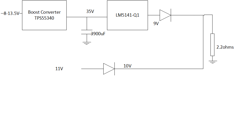
Im trying to build the hold up circuit design using TI Boost and Buck converter.The scheme is proposed below.

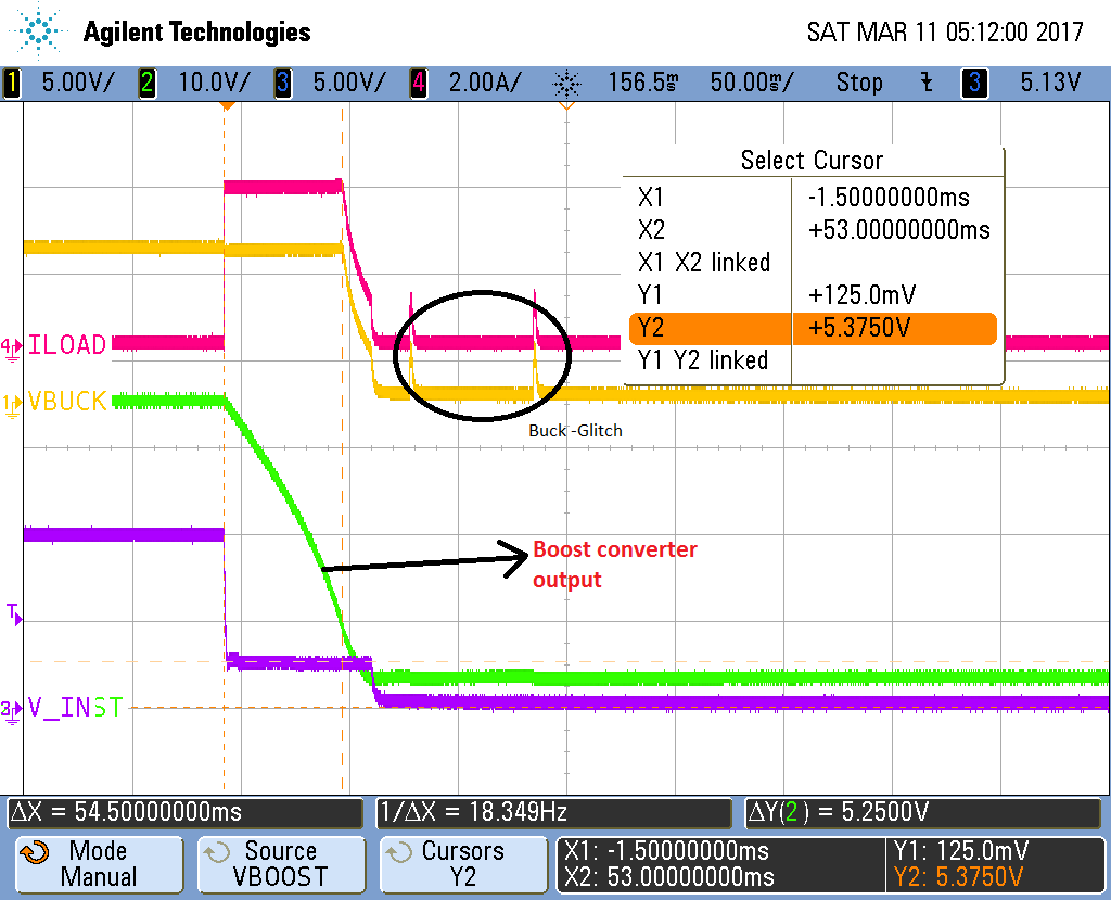
While testing the module individually everything works fine.When its integrated the Buck converter not responding properly.Buck converter should supply the power to the load when diode turns ON.The diode will turn on only when 10V goes below 9V .

Im validating this solution using TI eval board.I have modified the components based on the Webbench recommended component.

I have changed the L value from 2.5uH to 10uH,Rcomp=14.7K,Ccomp1=3.3nf,Ccomp2=2.7pF.

RFBT=71.5K and RFBB=11K

But not able to succeed it.

Can you pls help me in this.

Thanks-Arumugam

Can you pls help me in this.

  • Arumugam,

    Could you upload the schematics once again - because it's not visible in your post.

    Regards,

    Piotr

  • Hi Piotr,

    This is not the schematics.Im using the LM5141 Eval board.

    But I can show my architectural proposal.

    Thanks-Arumugam

  • Dear Arumugam,

    Is 9V present (and stable) when the output of TPS55340+LM5141Q1  is

    • left disconnected from any load?
    • connected only to 2.2Ohm resistor - without 10V power supply in the system?

    Can you check how LM5141Q1 switch node (SW pin) signal looks like during conditions above? Can you provide oscilloscope screenshots of that transition between 9V and 10V? 

    With information you have provided its hard to judge what can be wrong.

    Best regards,

    Piotr

  • Hi Piotr,

    I found out the problem in Boot strap section on LM5141.The LM5141 is damaged due to limitations in the power supply load current capacity.

    The power supply can support upto 5A and during power ON the inrush current is more than 5A and due to this the power supply entered in constant current source mode.So,the power supply voltage reduced to 7V .Hence Buck controller section ORing diode turned ON and reverse current entered into the Buck controller.Thats the reason Boot strap circuit damaged in the design.

    I replaced the device and used the higher current rated power supply.Now the design works as expected.But ,I found the glitch output at the Buck controller when the Buck controller turned off condition.

    Can you pls help me to solve this issue?

    Atttched the waveform

    Thanks

    Arumugam