A related question is a question created from another question. When the related question is created, it will be automatically linked to the original question.
If you have a related question, please click the "Ask a related question" button in the top right corner. The newly created question will be automatically linked to this question.
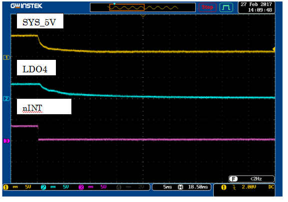
The pull up voltage of nINT should be always ON. As the PWR_EN low will disable LDO4, nINT will be driven low. On EVM, we have nINT pulled up to 3p3 rail from USB2ANY which is always ON.
nINT pin in this case instantly goes LOW. We have cases when nINT was not asserted and it would slowly drop with its pullup, LDO4. So, we believe that nINT in this case was asserted.
This is a symptom whenever we get an unintentional reboot during a shutdown routine.
Interrupt register says there has been an AC power status change (0x02). However, AC input in this case was a constant 5V. USB input is unused and connected to ground and BAT pins are floating.
Another thing to note is that the PMIC nWAKEUP output wasn't pulled LOW when nINT was.
*edit: Just to add, we have the nWAKEUP pin pulled up to LDO1 of the PMIC just like in the Beaglebone Black. But, if I understood the datasheet correctly this should be on an always ON source, so that it can be pulled LOW to signal a wakeup event. Would this be something of concern? We've recorded the nWAKEUP pin dropping with LDO1 on shutdown then going back HIGH after the system unintentionally reboots.
Can you re-create the issue while probing the AC and BAT pins with an oscilloscope? AC detection is dependent on the voltage of BAT, and a quick transient on the input supply could cause this interrupt.
LDO1 will stay active during sleep mode, but will not stay on in OFF mode. This can be seen in the Global State Diagram (Figure 20) in the datasheet - specifically note 5.
Jay suggests that since the pulse seen on Bat during the transition form Sys to Bat is only around 1ms this would not affect AC detection.
We have more details about the unintentional reboot on this thread. e2e.ti.com/.../570339
AC stays ON the whole time, but we've seen some noise on the line causing max short 400mv dips. We've suppressed these to less than 100 mV with some large bypass caps but still get the same errors.
We were able to patch the unintentional reboot and stop getting the interrupt event.
Our design has the AC input current limited to 1300mA. If we set this to 500mA (in PMIC register 0x01) just before setting the ALARM2 for shutdown, we do not get a reboot or interrupt.
Now we are wondering, why?
What has the AC input current limit got to do with AC detection? And why does limiting this to 500mA somehow solve our unintentional reboot when executing the shutdown command?
The following screenshots show a shutdown by disabling the AC power path in the PMIC registers. I had to use our test board, which has a problem with its RTC, for capturing the waveforms. Our "good" boards aren't allowed to be probed at the moment, so I was limited to disabling the AC power path.
Anyways, the AC power path disable method was showing the same interrupt and reboot behavior as the PWR_EN shutdown method. We've tested the current limit fix on our "good" boards, too, showing no interrupts nor reboot.
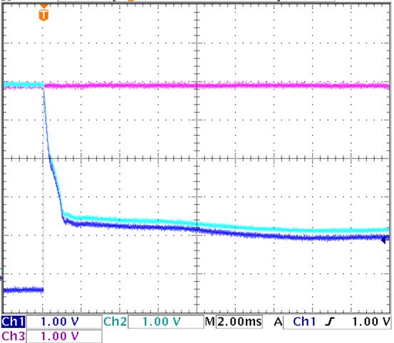
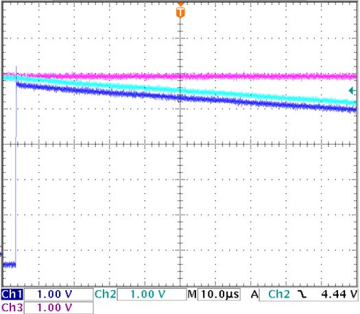
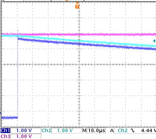
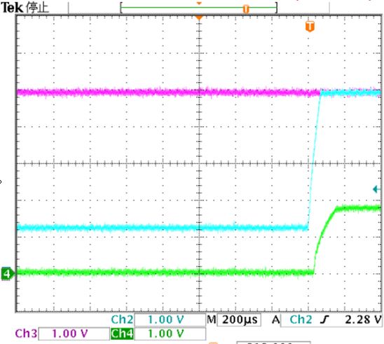
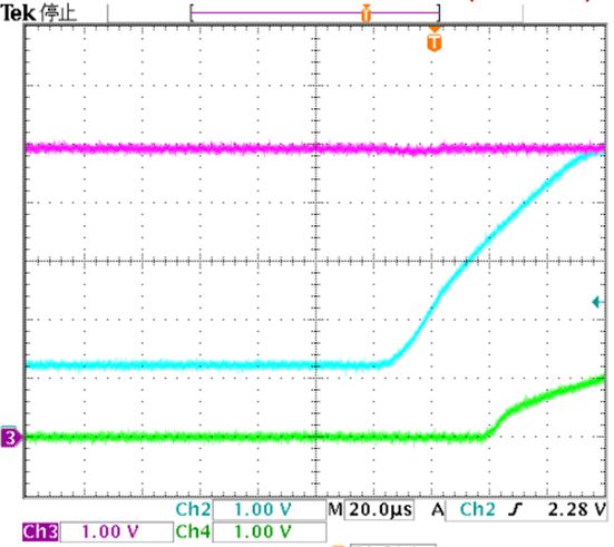
(Pink=VAC; LightBlue=SYS; DarkBlue=BAT)
AC current limit at 2500mA (reboot occurs after 1 second):
AC current limit at 500mA (does not reboot):
(*this last scopeshot was updated, wrong shot was initially posted, now it's ok)
We scoped a little deeper and measured the Rising Edge of the BAT pin in the reboot case rising about 4 usec earlier than when we set the AC current limit to 500mA.
Could it be that by decreasing IAC limit to 500mA, we are forcing IBAT to go below the termination current threshold therefore turning off the charger and somehow delaying the connection between SYS and BAT pins?
Interesting thing too, we tried disabling the PMIC charger by I2C register settings. If we disable the charger before sending a shutdown -h now command we will get the interrupt event and the system will reboot after one second of SYS dropping. But, if we disable the charger by writing to the register just before setting ALARM2 to signal a shutdown then we don't get an interrupt and the system shuts down cleanly.
I think this is hinting that the BAT charger is in someway interfering with AC detection.
Thank you for posting those captures. With the TS pin floating the charger should not be expecting a termination current, as this will be seen as an out of range battery temperature.
What are the functional differences between the shutdown -h now and using ALARM2? And does disabling the charger still work independently of the current limit?
You mentioned that the the AC current limit @ 500mA prevents the restart, but have you confirmed the AC detection interrupt is no longer firing? Does this still happen when experimenting with the charger?
-What are the functional differences between the shutdown -h now and using ALARM2? And does disabling the charger still work independently of the current limit?
Shutdown -h now and ALARM2 are essentially the same. The difference with the ALARM2 method I mentioned is that I manually implemented the routines of the shutdown -h now method and squeeze in the I2C register write just before setting the ALARM2. Biggest difference maybe is that some SW modules may not have been unmounted properly when I manually implement the ALARM2 routines.
-And does disabling the charger still work independently of the current limit?
Yes, disabling the charger just before setting ALARM2 for shutdown does work independently of the current limit.
- have you confirmed the AC detection interrupt is no longer firing?
I have confirmed that interrupt is NOT being asserted anymore during shutdown by probing the nINT signal. We have the PB_IN pin floating, so the only way to get the system back up is by unplugging and plugging the AC input. So, by doing this we'll see an AC status change.
-Does this still happen when experimenting with the charger? At the moment, I am unable to probe for this signal in this case. Because of some inventory issues.
Just disabling AC without a battery seems like it could cause odd behaviors, since there is no battery in the system to maintain the PMIC, but it seems like the current limit prevents a false AC detection, correct?
As for disabling the charger, since it still allows the PMIC to reboot when using "Shutdown -h now", but not with your manual implementation, it seems like a software issue. Maybe the DEV_OFF bit is not being set correctly and PWR_EN is being re-asserted?
If the current limit is the best workaround to prevent a false AC detection, is it an acceptable solution for these reboot and interrupt issues?
We are seeing the interrupt even with the PWR_EN shutdown method, we're just unable to probe the signals. AC disable method also results in an unexpected reboot after 1 sec. But, yes it seems like the current limit is preventing a false AC detection since we aren't getting an interrupt with AC disable or PWR_EN method of shutdown.
The current limit is an acceptable solution, but we still need to know why it seems to be preventing these issues.
If you're talking about the OFF bit in the status register, it is being set to 1 in both cases. I have an inquiry on the Sitarra forum about the PWR_EN being reasserted.
Is it possible that an interrupt signal, saying AC status change occurred, be caused by the PWR_EN being reasserted for about 10ms?
I can't see how PWR_EN could trick the AC detect interrupt, they are not very closely related. You showed that AC does not dip when the device turns off, but how close was the measurement point to the IC, and could there be a transient at any time during the following second?
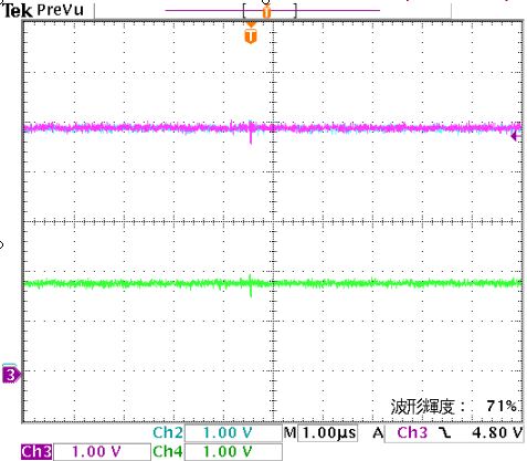
We were measuring from a wire soldered to the test point on the other side of the board around 5mm away from the IC pin, so pretty far. But, we tried again this time at the bypass cap about 1mm from the IC pin.
Here's a scope shot of the restarting part:
Pink-AC; LightBlue-SYS; Green-LDO1
I also tried catching any dips on the AC line by setting a 4.8V falling edge trigger on the AC signal. We would see small drops of about 200mV for about 25nsec. We've actually been seeing this all over the AC line before but figured that it's too small to cause an AC detect. We also see this noise on our other Beaglebone based projects that don't reboot on shutdown.
How small can a dip on AC be to trigger an AC detect event?
Removal detection voltage threshold for a no battery application like ours would be 3.5V and below - far from anything we're seeing on AC. But if the spike on BAT pin is indeed interfering with AC detection, then removal detection voltage threshold would be VAC - VBAT < 125mV. I understand the detection deglitch is 22.5ms, but if I understood the datasheet correctly this isn't applied to removal detection (I'm not so sure)? So let's say VBAT was greater than VUVLO(3.5V) for around 200uS during the BAT pin spike on shutdown. VBAT just has to be greater than 4.875V to satisfy a removal detection, which it seems like it's doing for about 10usec more or less.
The confusing part is, we've recreated the BAT pin behavior on one of our other boards, but didn't get a reboot on shutdown.
Experimenting on an EVM, if I disable the AC power-path and then use the push-button to restart the PMIC, the PMIC will register an AC detect interrupt rather than a push-button interrupt. This may be due to the way the part handles a fault event, where the following wakeup event actually resets the device.
Without a battery a dip would have to go below UVLO+offset, where UVLO has a 4 to 6ms deglitch time and is configured by the UVLO register.
That is interesting. I think we'll have to look more into our PB_IN pin again. Although, even on a PWR_EN triggered shutdown we still get the AC detect interrupt.
PB_IN in our case is floating. During shutdown, the 5V on PB_IN drops to around 3.8V. We've tried pulling this up to AC voltage to prevent the drop, but still get a reboot.
In the case where there is a battery, does the 22.5ms detection deglitch apply to AC/USB removal detection?
I also tried one of our other project boards that does not experience this reboot issue and has a power button installed. I disabled the AC power-path and then used the push-button to restart the PMIC. I would get 0x06, which says both AC-detect and Push-button detect caused the interrupt.
The 22ms deglitch does not apply to the AC to BAT transition, this transition happens almost immediately when AC is equal to BAT, where AC = BAT + 125mV was only a few microseconds before the transition.
When my PB pulse is ~100ms, I only get the AC detect interrupt, but holding the PB pulse for ~200ms I am also able to get both PB and AC interrupts.
Thanks for that information.
Could you try a shutdown by pulling PWR_EN low (with OFF bit =1), then doing the same ~100ms PB pulse? If it yields the same result (AC detect interrupt only) then it would make PB_IN a highly probable cause. If you could try even shorter pulses that would be great.
But, seeing that even on a PWR_EN shutdown we still get the AC interrupt, we are still left wondering where the AC interrupt, that's causing the reboot on shutdown, is coming from.
So far (what I can think of) the causes of an AC interrupt would be:
-A dip in AC voltage lower than 3.5V [ we don't see anything close to this (even probing at the bypass cap right next to the pin) ]
-VAC - VBAT < 125mV if VBAT is > 3.5V [ BAT, BATSENSE, and TS are all floating, but we see VBAT going higher than 3.5V for a couple milliseconds, we've also replicated this behavior on another similar project but don't get the reboot ]
-and that's it.
Should we be looking elsewhere? Could the AC interrupt signal be an unintentional side effect of some other symptom that's causing the reboot? Could it be current behavior instead of voltage? Should we be looking more into the layout?
We really appreciate all the help. Thank you very much!