


I have been using this buck controller for 4 buck regulators at different voltages, thru three rounds of board build (over 1.5 yrs. span, with no change to the SMPSs layouts).
The one regulator which now has excessive ripple approx. 100-200mV (0-2A load) is the 6V out with 28-38V input, which when looking at the SW node has Fsw - (70-100KHz), board is designed for 318KHz.
For this round of 50 boards about 20 are switching at 1/3 the designed Fsw. I have checked the components on several boards, compared the node voltages to a good switching board, etc. with no differences and all components seeming to be correct per the design. I tried to change the Fsw by changing the RT resistor but it doesn't change the Fsw. Checked the SW node for ringing -overshoot => very clean maybe 500mV overshoot but no ringing.
Checked to see if the OCP or SCP was kicking in, maybe higher FET Rds on, increased it by a factor of 2 and the multiplier from x3 to x7 => no change.
Lifted the inductor to add a current loop wire to check inductor current => Good switching at design Fsw= 318KHz.
Compared comp. signal between bad board with low Fsw = 100kHz and good board = 318KHz and the comp signal is ramping from 0-2V , but is normal opn good board at Voffset = 1.5V and 500mV ramps each switch cycle.
Have done extensive simulating for stability and performed loop response testing on three board, same layout design about 1,5 yrs. ago, with simulation=>. Fco = 40KHz, Phave margin => 65 deg.
and loop response on the board => Fco = 50KHz, Phave margin => 73 deg..
Has anyone seem a similar or related issue with a reduction in switching freq., etc. when using this SMPS buck controller.
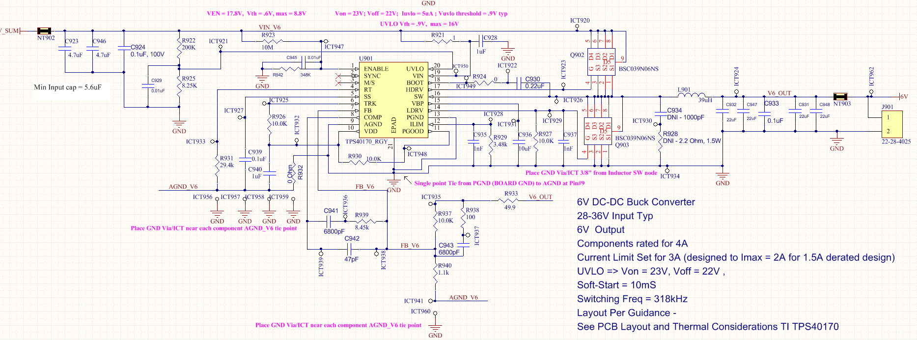
Schematic below:
Thanks,
ERIC F. KING
