This thread has been locked.

If you have a related question, please click the "Ask a related question" button in the top right corner. The newly created question will be automatically linked to this question.

LM3409HV: Does it can driver output current of 3A

Part Number: LM3409HV
Other Parts Discussed in Thread: LM3409

hello!

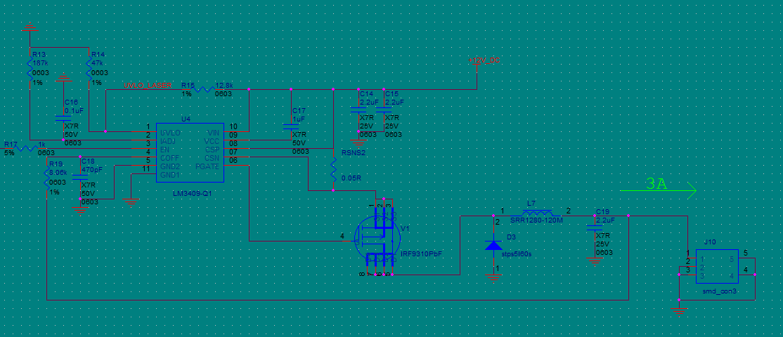
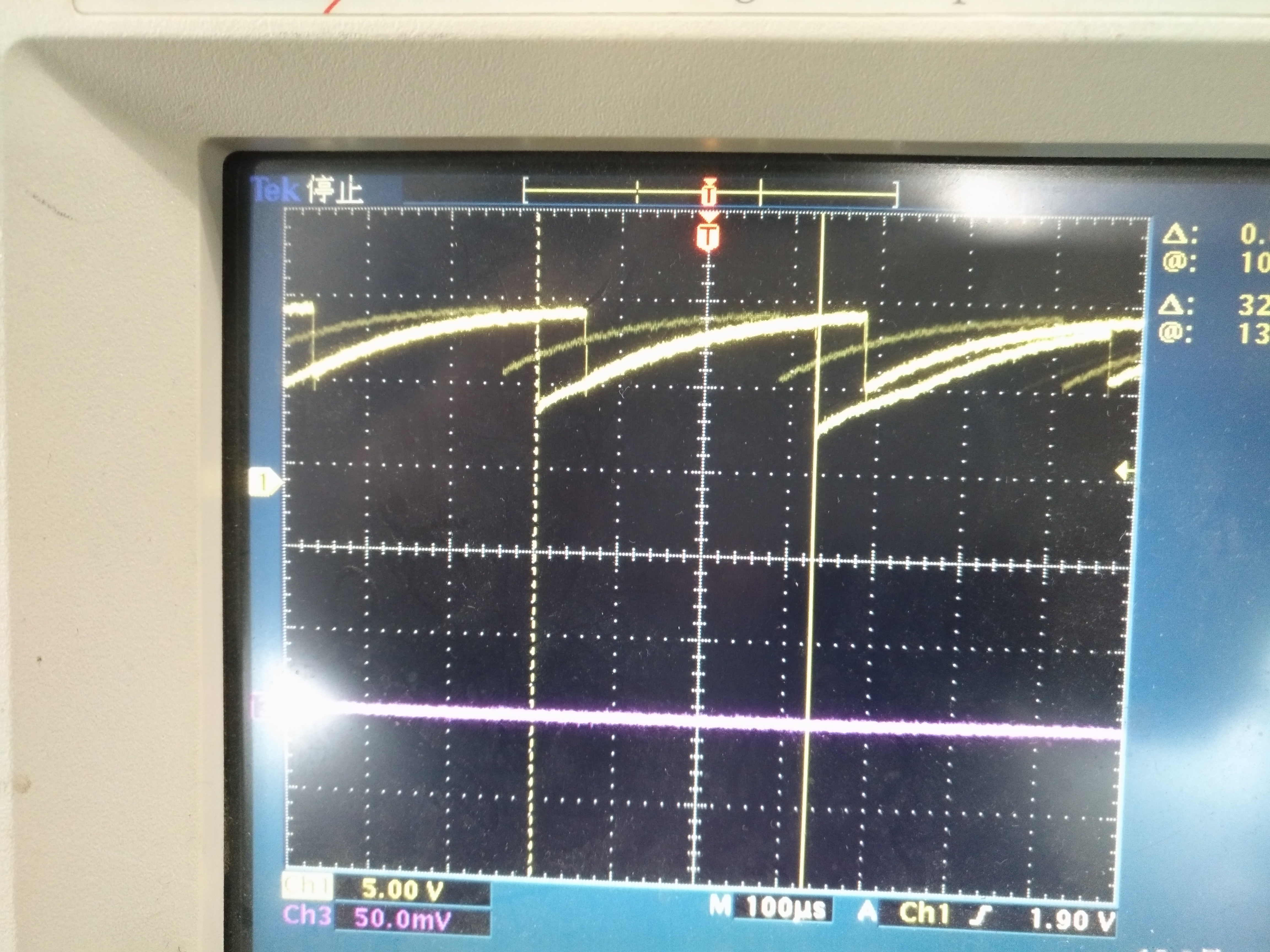
    I want to use the chip lm3409 driver LED output current of 3A with6V,but It didn't seem to work properly Switching frequency is not normal .

I guess is  inductance and switch off resistance of hardware configuration is not correct.ut not so sure that this phenomenon caused by inductor saturation.can anyone give me some advice in this scheme.I not sure which parameters can be replaced that can have 3A with 6v output current.

thank you for your help!

.

  • Hello,

    First I would make sure the 12V input supply is not current limiting, it should be capable of at least 3A. Layout issues can also cause things like this and that is something we can explore further if need be. But I believe in this case it is likely the FET you are using. I looked it up and it specifies a gate charge (Qg) of 165nC which is quite high. It also looks like you are trying to get a switching frequency of around 500kHz. This means the current draw from VCC would be almost 83mA (Ivcc = Fsw*Qg), but the VCC current limit can be as low as 30mA with 45mA typical. So you will basically collapse VCC when trying to switch. Try using a FET with a Qg of 60nC or less and see if the results are better. The LM3409 is simply not capable of driving that FET that fast.

    Regards,

    Clint

  • Hello!

         I'm sure input suppy is not current limiting because i used a large enough DC supply.and This circuit and device configuration can achieve stable 2A output.

    If i change the sense resistance to 0.05 ohms In order to get 4A output,than Switch waveform phenomenon is just like you said state of collapse.

    So I agreen with yours idea ,maybe the FET with a Qg of 165nc is quite high.l  try to use other FET such as FDS4435 which Qg of 40nc that wish can work normally.

    I always have a question that the chip's Duty ratio  Relationship between inductance and cut-off Resistance,how can i choose the paramater if i need  different max current case.

    I wish you can give me aParameter selection scheme for reference.I will continue to debug to find reasons.

    Hope to get your continued help.

    Thank you!

  • Hello,

    I am not 100% sure what you are asking. What cut-off resistance are you referring to? Is this for true zero current? Or are you just wondering how to calculate inductance?

    Thanks,

    Clint

  • hello!

    sorry,

    I express may not be clear,As mentioned in the Schematic diagram of hair,cut-off resistance are referring to  R19. I just wondering how to calculate inductance and this resistance.

    My goal isMake a circuit design do 3A output current by use lm3409.So hope to get a reference scheme with 12V input and 3A of 6v output.

    Bye the way,recently I found the if EN pin output impedance condition is not stable .Sometimes have output current sometimes cutoff, is not always should be shut off if this pin In a state of floating empty or grounded?

    thanks.

  • Hello,

    You use equation 1 in the datasheet to calculate D = 6V/(0.9*12V) = 0.556.

    Your off time is 1-D/Fsw. So if you want 100kHz switching frequency toff would be (1-0.556)/100k = 4.44us.

    Use equation 4 (toff equation) to calculate Roff.

    Then use equation 7 (deltaiL-PP) to calculate the inductor value to get the inductor current ripple you want.

    The EN pin is high impedance, low current so it cannot be left floating. If it isn't used it should be tied to VIN or its state will be unknown and could fluctuate.

    Regards,

    Clint