This thread has been locked.

If you have a related question, please click the "Ask a related question" button in the top right corner. The newly created question will be automatically linked to this question.

LM5007: IC blew top off after years and replaced IC, switcher bucks +24v to +5v yet it seems noisy.

Guru 56033 points
Part Number: LM5007


Hi everyone,

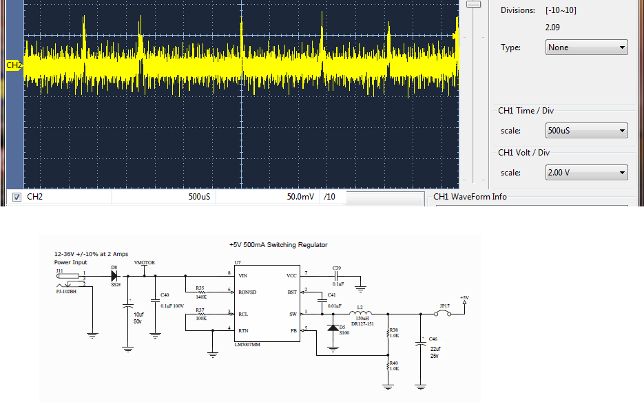
Can someone tell me if +5vdc output seems abnormally noisy? Powered by a +24v off line switcher also powering an inductive motor load with 470uf at inverter PCB

The +5 is bucked again by 3v3 LDO (TPS73733) and it seems to cause a 50mv PP ringing on +3v3 that gets into all MCU peripherals.

What should I check for being bad LM5007 circuit, Schottky D5 checks ok on diode check, C46 22uf SMT Panasonic can type electrolytic tests Ok cap checker and 10uf can type at input is newly added.

There is also 3/4 amp series fuse added on PCB after the polarity diode D8. Switcher PCB was part of an RDK, cut off to use with another project.

Capture shows LM5007 idle mode no motor loading +24v.

TPS73733 +3v3 output seem to have a bit to much ring or is this industry acceptable DC?

  • BTW the LM5007 unloaded output voltage is a datasheet match except for a lot of ringing on the down slop of the FET avalanche. Checked the circuit again and there are no open grounds or incorrect R values, also added 10uf to the output which reduced the PP noise. That did not stop the TPS73733 output from ringing.
  • Hello,

    The schematic you posted looks OK. Following comments:

    1. i suspect VMOTOR could be very noisy. some additional filtering with increased input capacitance and additional smaller capacitors (100nF/10nF) should help.
    2. suggest trying larger inductor value. quick webench check resulted with 220uH inductor value for your use case
    3. adding small capacitor in parallel with existing output capacitor (100nF or 10nF) should help improve performance
    4. make sure when measuring output ripple that it is measured directly across output capacitor using good quality differential probe
    5. layout can also have significant impact on part performance. it would be good if you could share your layout for review and comments

    Best regards

    Brani

  • Hi Brani,

    Thanks for reply help.

    Brani Dubocanin said:
    suggest trying larger inductor value

    Oddly the LM5007 regulator PCB came from an Motor RDK and seemed to be ok in that circuit with different +3v3 LDO. The +5v also boosts to +15v in same PCB area via FAN6331 but it seems ok with a 22uf can on the output.

    I added a double sided 1/2" diameter toroid (assuming 25-40h ??) at the +/- DC connector and it made no difference. There is a 12.5Khz flyback pulse bleeding into the +24v supply every 150ms or so but don't think that is causing the down slope ringing of the LM5007 FET. Just to be sure was not the offline +24v switcher, replaced with two 12v batteries in series. Same ringing was present in the output and so was that dang PWM inverter flyback from high side FET's switching.  

    Brani Dubocanin said:
    quick webench check resulted with 220uH inductor value for your use case

    Very interesting and will upgrade to 220uf but does that change other C/R values in the output?