This thread has been locked.

If you have a related question, please click the "Ask a related question" button in the top right corner. The newly created question will be automatically linked to this question.

LM3404HVEVAL: LM3404HV

Part Number: LM3404HVEVAL

Hello,

I need to design a simple constant current source which is not intended to drive LEDs but instead a water electrolysis.

I thought I could use the LM3404HV, because I have 48V Input Voltage given.

The constant current should be at 0.7A.

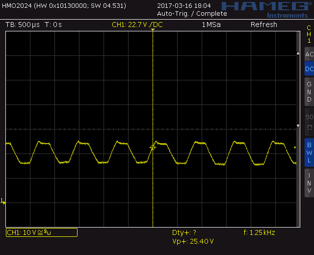
Now when I load the LM3404HV Evalboard with a resistor of approximately 33Ohms I get a nice flat output Voltage.

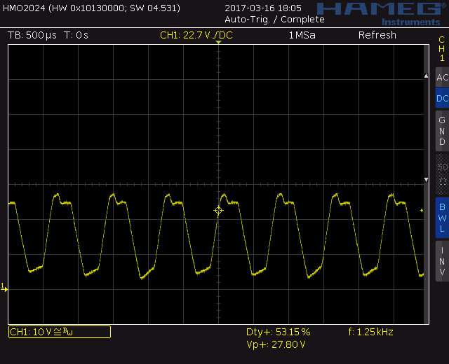
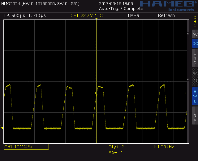
If I reduce the Load Resistor the Output Voltage starts to oszillate at 1.25kHz until the low Level even reaches GND.

It then looks almost like a triangle waveform.

What am I doing wrong? Does this chip not act as a constant current source when driving higher loads?

  • Hello Markus,

    Is there any way you could share the output voltage and SW node voltage waveforms at 700mA and at the higher current? It should be able to do up to 1A but using a resistive load may affect this. A resistor voltage will follow the current ripple directly where an LED voltage will remain fairly constant. I can't be sure without waveforms but I suspect that might have something to do with it. I could be affecting BOOT or maybe it is affecting the shunt FET through parasitics due to the high ripple voltage? The first things I would try would be to remove the shunt FET from the board and populate Co1 to give you a more stable output voltage and see if that helps. Otherwise I can take a look at the waveforms to see if they tell me anything.

    Thanks,

    Clint

  • Hi Clint, Thanks for fast Response!

    Actually I have already built my own PCB without that shunt FET.

    I have populated a Resistive shunt with 0.33Ohms on the eval board and my own circuit.

    Both behave almost the same.

    This is the waveform with a 40Ohm Resistive Load:

    If I reduce the Load Resisitor further it looks like this:

    even more like that:

    BR Markus

  • Hello Markus,

    What do you mean by a 0.33ohm resistive shunt? What value are you using on CS? Did you try using an output capacitor? As I mentioned the LM3404 is meant to regulate current but is also assumes an LED load will have fairly constant output voltage. If it doesn't like with a resistive load that doesn't have enough output capacitance it looks more like a resistor divider where as you lower the load resistance it takes a higher portion of the ripple. In the last case it looks like it has gone discontinuous.

    I any case if you can let me know what mods (if any) you made to the EVM I can take a look at one here if increasing co1 does not help things. I am also curious as to why the on time is so long. Will the end load behave more like an LED or more like a resistor? If more like a resistor then a current mode device like the TPS92515 might be a better option.

    Regards,

    Clint

  • Hi Clint,

    I ment the Rsns has been modified to 0.33 Ohms to provide around 0.7Amps.

    You are right, I did not use any additional Output Capacitor. I tried to use a 220uF Electrolytic Cap. Now it seems to work almost properly.

    The EVM was a normal LM3404 board where I soldered a HV chip onto it. (Did not get the HV Version in short Term). Two additional things I changed was the Rsns to 0.33Ohms and Ron to 100k.

    The real world application are electrodes which are used for Electrolysis of water! So the load may be very different according to the dissolved solids in the water which is treated.

    I would really appreciate to get the LM3404 working for my purpose since it is already used on my custom PCB. But thanks for suggesting other devices.

    I still have two issues to work on:

    The current is not very constant, it varies between 0.65 and 0.75A when increasing the load. Maybe this can be improved, but it is not THAT important.

    The Maximum Voltage at no load (or very light i.e. 10kOhms) is around 32Volts where the Input Voltage is 48V!

    I increased the Ron to 180k so that the Vomax is around 35V now.

    But even more VOut would be nice. How far can I increase the On-Time by setting the Ron? What would you suggest?

    What is the best value for the COut to be used?

    Thanks, Markus