


Sometimes the output logic is different from the input condition.
(Please see the figure below)
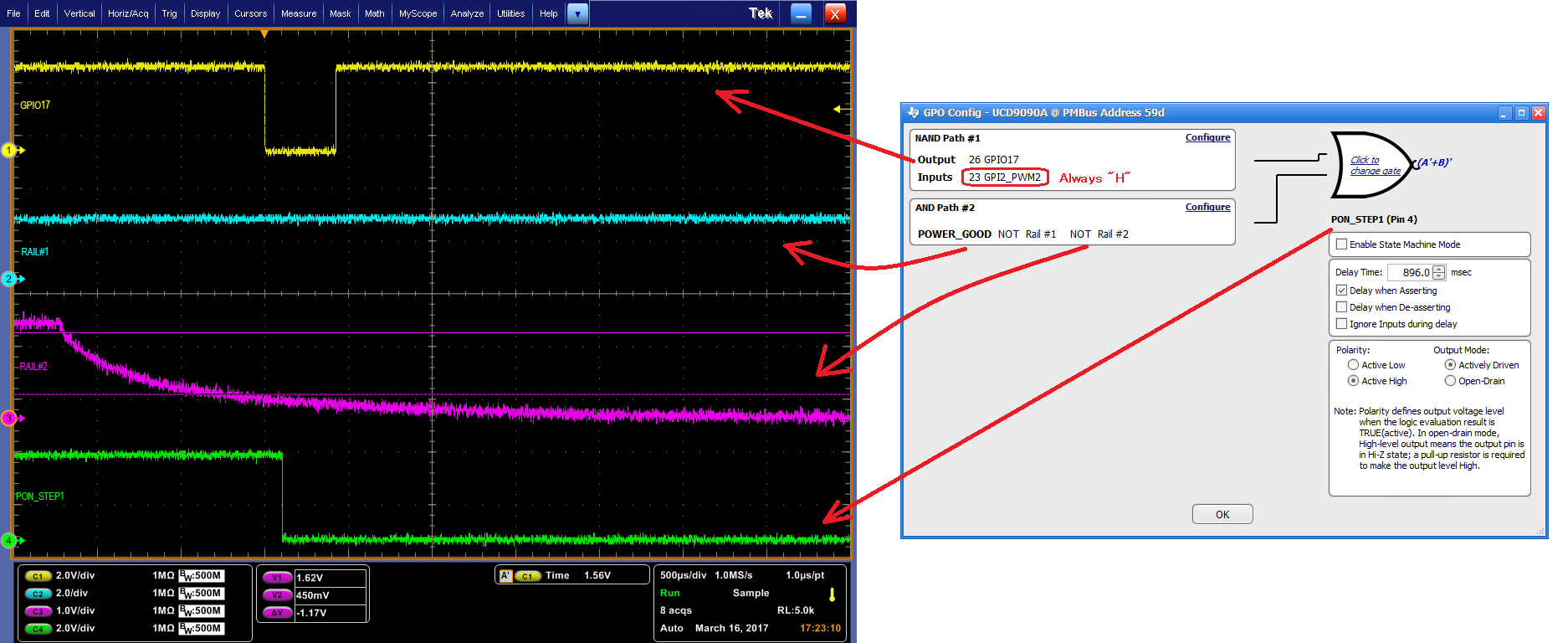
Normal case
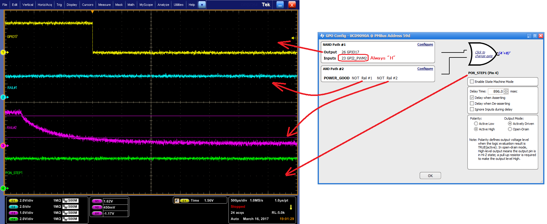
Abnormal case
In normal operation, the operation that PON_STEP 1 goes "L" when GPIO 17 goes "L", but PON_STEP 1 does not go to "L" but remains "H" in case of abnormality.
This phenomenon causes the system to stop and become a problem.
Is this phenomenon reported as occurring in other equipment as well?

