This thread has been locked.

If you have a related question, please click the "Ask a related question" button in the top right corner. The newly created question will be automatically linked to this question.

LM5160: method for reducing noize

Part Number: LM5160

Hi,

As a result of carrying out the EMI test, noise of Class A or more appeared in the 100 MHz to 200 MHz band.
The cause is that noise is generated when the high side FET turns ON.

Noise could not be reduced with the following contents.
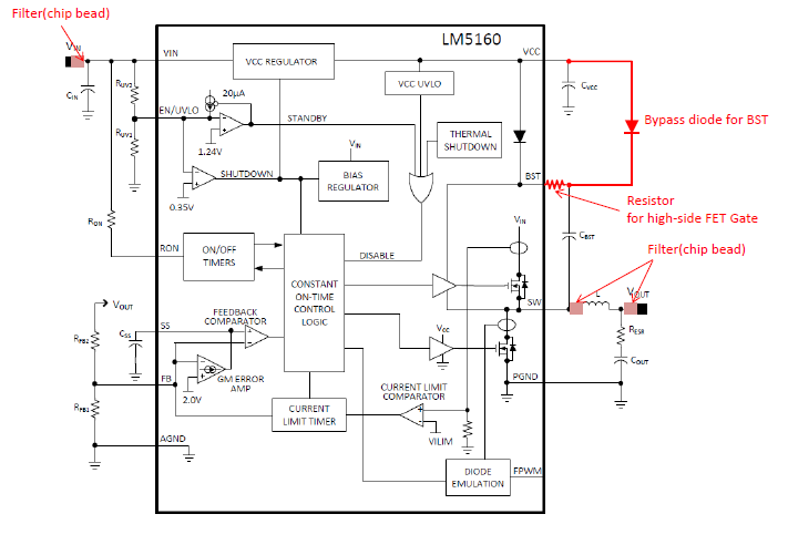
Ferrite beads are placed before and after the inductor.
Place ferrite beads in VIN.

When the gate resistance and the diode were put in the BST pin, the noise was reduced below the standard.

Are there any problems in operation by adding parts (red) with the circuit shown in the attached drawing?

Best regards,

  • Hello Kaji,
    I don't see an issue with the additional component placements. You will need to confirm that these additional components are right for your application. I would however, place the Resistor in series with the other side of the boot capacitor , that way you can ensure external Boot diode always conducts during the 1-D period by correctly bypassing internal boot diode.
  • Thank you for the advice.
    Is it the position of the resistor, is it added to the current circuit to the blue position in the figure below?

    The external resistance to the BST pin is 51 Ω.
    There is almost no drop in efficiency, but is there any problem?

    The external diode to the BST pin uses "DA 2 J 10100 L".
    Is there a problem with the type of diode (switching type)?
    What is the required rating current (IF, IFM, IFSM)?

    Best Regards,

  • Yes, place boost resistor as shown in blue.  51 ohms is too large and will adversly effect efficiency.  I would use, say 5.1ohms and use an RC snubber from Switch node to Gnd as an alturnative approach. Start with 1 ohms (Rsnub) and 100pF(Csnub) and start increasing the 100pF to 1nF, keep an eye on the thermals of the Resistor as you increase the Csnub cap to 1nF.  Use a 0805/1206 size resistor for thermal control.

    The Boot Diode should be an Ultra fast Diode, with Trr<50ns.  The datasheet does not appear to provide the Trr, but the junction capacitence looks fine.  the reverse currents looks like 100nA, which is good.  The repetetive currents, looks a little low.  But you can quickly tell if this is ok, but checking the temp rise of the Diode.  I would use a diode that has a peak repetive current of ~500mA to be safe?  But this diode you used, maybe just fine, please check temp after running for a long period of time.