This thread has been locked.

If you have a related question, please click the "Ask a related question" button in the top right corner. The newly created question will be automatically linked to this question.

TPS720105DRVEVM: Determine if an LDO can be damaged or weaken

Part Number: TPS720105DRVEVM
Other Parts Discussed in Thread: TPS720

We need to determine if applying voltage from a single AA battery to the output of the LDO, when there is no power or connection applied to the +3.3, would damage the LDO in the following configuration. We have no reported failure, but we need to determine if it is possible to weaken or damage the LDO.

For reference we are using a 1.5 V AA battery to do a quick check in production that the motor is functional. The LDO is a TPS7201Q.

Thanks

  • Since the screen capture of the schematic didn't show in the previous post and to clarify some points.

    The input voltage is from the 3.3V rail thru a reverse polarity diode to the input of the LDO.

  • Hi David,

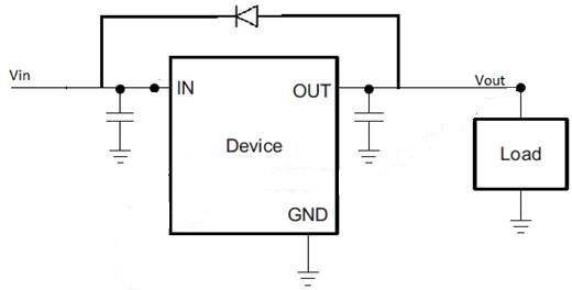
    Anytime that Vout exceeds Vin there is the potential for reverse current.  While TPS720 has a body diode that will conduct this current from Vout to Vin, the current will not be limited.  If extended reverse voltage operation is expected, an external diode can be placed parallel to the LDO in order to provide a robust path for reverse current.

    Very Respectfully,

    Ryan

  • Ryan,

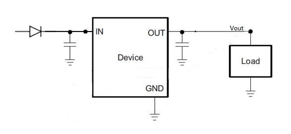
    Thanks for the feedback. I see where you are going. My question would be, if there is a diode in series between the Vin and the IN on the part. The diode's cathode would be connected to the part and the anode on the Vin. Wouldn't this block any reverse current flow between the output of the part and the Vin?
    When looking at the datasheet, we seen the diode across the internal FET. But with the external diode described above, there wouldn't be a current part back to Vin.

    Thank you again for your time.

    Dave

  • Hi Dave,

    I think you are describing this configuration:

    In which case and long as the input capacitor is sufficient (i.e. as recommended n the datasheet). There is no problem with putting a diode in series with VIN as shown above. 

    Does this answer your question?

    If not, please let me know if I am unclear on your question.

    Thank you,

  • John,
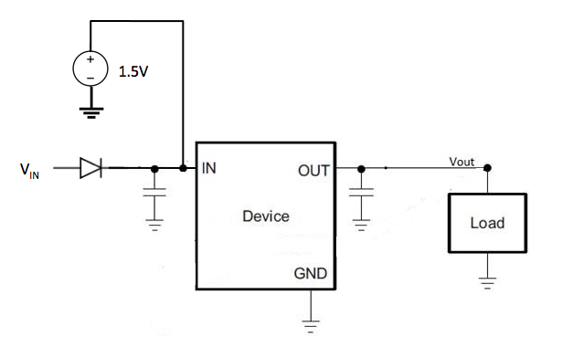
    Would it be safe to apply 1.5 volts to the output when the Vin supply (anode side of you diode above) is off? We are trying to apply power to the load when the board is not powered.
    thanks
    Dave
  • HI Dave,

    This really depends on your 1.5V supply. Is there a potential for VIN to be applied at a higher voltage?

    If the 1.5V input source can handle a higher VIN, then this can work.

    Am I understanding your concern properly?

    Thank you,

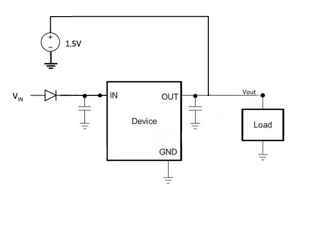
  • I don't think so... The 1.5V is across the load only. We have a small tactile motor as the load in our circuit that we are trying to test in production during assembly. We would like to apply 1.5 v to the motor only, from a AA battery... We are trying to verify the motor is functional after gluing it to the PCB without having to supply the power to the main circuit of the board.
  • Thank you for your clarification. If this is what you are doing:

    As long as you do not violate the absolute maximum output voltage our device, we are OK.

    Does this answer your question?

    Thank you,

  • I believe we are on the same page.
    Thanks for your time!