This thread has been locked.

If you have a related question, please click the "Ask a related question" button in the top right corner. The newly created question will be automatically linked to this question.

LM2588: Chip randomly starts up in stuck mode

Part Number: LM2588

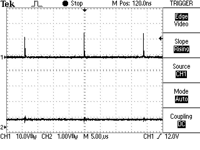
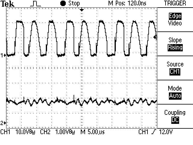
I have a simple flyback transformer based boost supply built around an LM2588, and noticed it would occasionally start up in a mode where the circuit would draw excessive current.  Originally, it would recover after a short while and operate normally, but while debugging the problem, I tried adding a separate power supply for the LM2588.  Sometimes it will start up and work properly, but other times, it ends up in one of two modes where the SW pin stays low most of the time (drawing high current, saturating the transformer, and producing low output voltage).  I have a 22k resistor to the frequency adjust pin to set the operating frequency to 200kHz.  When it's working, it works nicely at this frequency.  When it gets stuck, one mode is at 200kHz, but the "compensation" pin is at about 2.6V, the other stuck mode is at about 53kHz, with the "compensation" pin at about 0.4V.  I've tried several of the remedies in the data sheet, including adding a Schottky diode to clamp negative transients on the switch pin, changing the compensation network, and adding an RC low-pass filter to the Vin pin.  None of these avoid the problem, it still powers up in one of the stuck modes occasionally, and now that it has a separate clean Vin supply, it doesn't recover (I think it recovered initially because the power supply would current limit to 1.5A, which would drag Vin down from 12V to about 4V, whereupon it would shift to a different mode and begin working properly after 500ms - 10s or so).

  • Hi John,

    Sorry to hear you're having issues. If it is possible can you please post a schematic of your design. Also can you provide the input voltage range, output voltage and load current specifications for this design?

    When you say that " I tried adding a separate power supply of the LM2588" does that mean that a supply is just being attached to the VIN pin? Please also provide any waveforms that you might have of the two conditions that you described above.

    Thanks,

    Garrett
  • Here's the switch output low, at a low (~53kHz) pulse frequency (top trace), and the compensation pin (bottom trace):

    Here's the switch output low, at the selected (200kHz) frequency (top trace), and the compensation pin high (bottom trace):

    Here it is operating normally with the SW input switching at 200kHz with a reasonable duty cycle (top trace), and a signal with a little AC at an intermediate level on the compensation pin (bottom trace):

    These are taken with the Vin pin powered by a separate 12V bench supply (as you surmised).  The transformer is being supplied with 12V as well, from its own bench supply.

  • Hi John,

    What is the transformer part number? Can it handle the 5A current limit that is on the LM2588 switch pin? Just to clarify this only happens during start-up, right? If this is during start-up it could be related to the inrush current.

    Thanks,

    Garrett
  • The transformer is a custom unit by Custom Coils. I doubt it can manage 5A continuously. Initially, this behaviour only happened during startup, the bench supply would current limit, the voltage would sag to about 4V, and the LM2588 would recover after a little while. However, when I gave the LM2588 a separate, stable supply, the behavior sticks. It will operate indefinitely in one of the three modes. Each time I power it up, it goes into one mode or another (apparently at random) and stays there.
  • Hi John,

    Here are a few other things to look at.

    1. Is the IC increasing in temperature? This would indicate that the IC is in current limit since the switch is internal.

    2. Does this happen at different VIN and VOUT combinations?

    Thanks,

    Garrett