This thread has been locked.

If you have a related question, please click the "Ask a related question" button in the top right corner. The newly created question will be automatically linked to this question.

CCS/TPS54320: TPS54320 slope compensation parameters

Part Number: TPS54320
Other Parts Discussed in Thread: TPS54620

Tool/software: Code Composer Studio

Hi team,

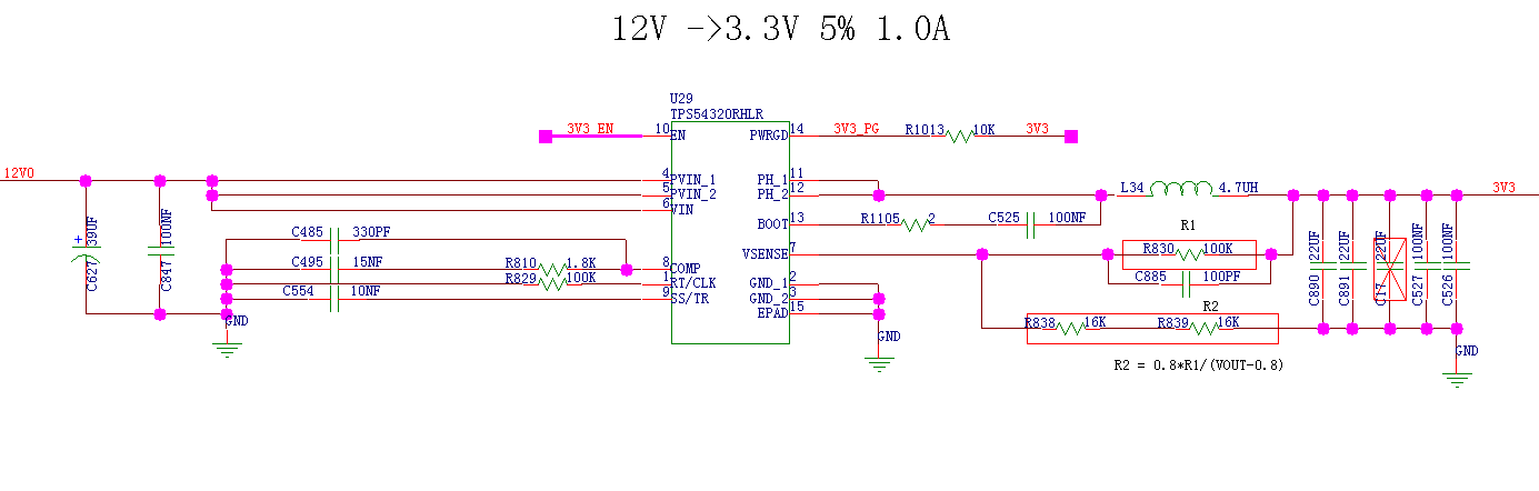
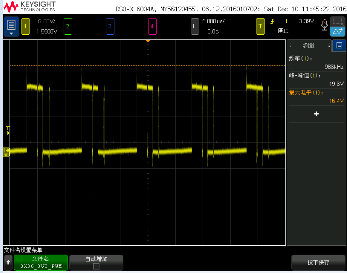
My customer wants to use matlab to simulate the TPS54320 BODE plot. We don't know the slope compensation parameter from the datasheet. Could you please share me the spec about the slope compensation?

Thank you.

BR

Frank

  • The parameters are:

    Se = 6*Fsw*Ri and Ri = 1/12

  • Hi John,

    Thank you for your help. My customer is using the chip now. And meet unstable problem.

    The schematic is below.

    The SW waveform is below.

    From the SW waveform, it seems the converter isn't stable.

    So we do the bode plot analysis.

    When use our TINA. The fo is 54khz, phase margin is 71 deg. gain margin is 15db.

    When use matlab to simulate, the f0 is 50khz, the phase margin is 70 deg. gain margin is 17db. (Se is based your reply)

     They both seem to be stable. We think the unstable is caused by the Se not working.

      Do you have some ideas about this problem?

    BTW: Does the TPS54620 have the same Se with TPS54320?

    Thank you.

    BR

    Frank

  • I get Fco = 57 kHz and PM = 66 deg.  It should be stable.  Your input capacitor appears to be electrolytic. You need 10 uF or more X5R or better ceramic capacitor right at the VIN pins to ground, very close to the IC.  You may have layout issues as well.

    Slope comp is probably different for TPS54620.  I know for a fact the power stage transconductance is different.