This thread has been locked.

If you have a related question, please click the "Ask a related question" button in the top right corner. The newly created question will be automatically linked to this question.

LM25119: CC to CV transition unstability

Part Number: LM25119

Hi,

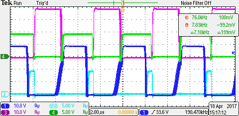
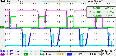
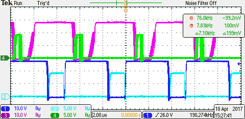
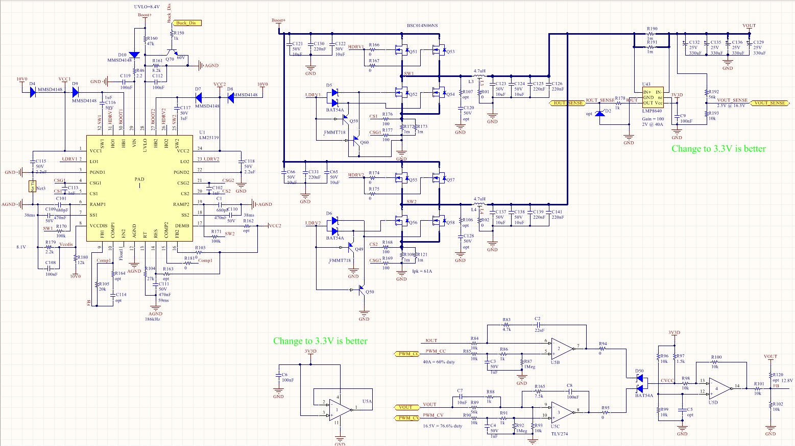
Application is for 12V battery charger. Input is 16V-36V. Output is 40A. Issue occurs when battery voltage is approaching the CV level and CC control is transferring to CV.

  • Hi Paul,

    Difficult to say exactly what is the root cause of your issue.  I would suggest, to make troubleshooting more manageable, to separate the CV and the CC modes.  By this I mean, have you confirmed that both modes are stable?  Suggest load stepping a CC mode by stepping the voltage and monitoring the current response and also check CV mode by stepping the current and monitoring the voltage response.  I suggest checking both modes in this way to ensure they are both stable.

  • Hi David,

    The issue is most likely in CC mode. At room temp, the unit works fine using eload at CV mode. Can deliver 40A up to maximum output voltage setting and decrease load current afterwards. Same testing but at 50C ambient, then the unit becomes unstable when near the maximum output voltage setting.

  • I would look at installing Rcomp and Comp, I am not sure your supply is stable in this configuration?  First, please try load stepping in the CC mode and see if the load current is well damped, you do not need a huge load step to determine this.  Just a small about and see if the load current oscillates at it settles to the set level?

  • Hi David,

    I found that the power limit is hit at 50C causing the previous issue. I changed the sense resistor to 2x 0.5mohm and the power limit is avoided. However, I observed in other unit that low_drive in one of the phases is terminated earlier causing lower efficiency at some conditions.

  • Hello,


    Are you saying that you have programmed Forced CCM mode by connecting DEMB to VCC, however you are still operating in Diode emulation mode on one phase?  Also are you saying this is only happening on one of your boards?  Please clarify, thank you.

  • DEMB is left floating (pull-up resistor un-mounted) to avoid reverse current direction. Diode emulation is enabled but the low_drive early termination occurs at full load current of 40A. Waveforms are tested on different input voltage. This issue is very visible only in one unit since the pulse duty difference is huge. It happens either in the master phase or the slave phase.
  • Hello Paul,

    Thanks for clarifying DEMB condition.  when you say it happens on one board, do you have boards where it is working fine?

  • Hi David,

    In some board the difference in the duty cycle of the 2 phases is not that big. But in this one board, one phase will have shorter pulse and can be either the master or slave phase.

  • Hi Paul,

    OK, sounds like you have poor load sharing in one board?  When you say load "hogging" can either be in the master or slave.  What are you doing differently to change from master or slave hogging current?

    Thanks.

    David.

  • Hi David,

    In the waveforms I sent, the difference is just the input voltage. It's already steady condition with 40A static load using eload set at 13V CV mode. 

    Another condition is at constant input voltage and ramping load current. Eload set at 13V CV mode and the CC reference is ramp at 10A/s. During the ramp, one phase will hog the current and then when reach the maximum 40A the other phase will take over to hog the current.

  • Hi Paul,
    I am sorry, it’s difficult to follow exactly what is happening here, but if you have one board that is not working right, while the other boards are, I think the easiest approach is to look for difference in the build of the boards, i.e. components installed, to see if there is an error of some sort. If this is confirmed to be right, I would swap out the ICs from the good board to the bad and vis versa and see if the issue follows the devices? if it does, we can further trouble shoot this approach, if it does not, then I would take a closer look at the differences in the components installed and measure and compare voltage levels and see if you can pin point where the differences are coming from, I would start at the feedback control loop and work out from there.