This thread has been locked.

If you have a related question, please click the "Ask a related question" button in the top right corner. The newly created question will be automatically linked to this question.

BQ40Z50-R1: Present function questions

Part Number: BQ40Z50-R1

To whom may concern:

We are using BQ40Z50-r1 in a battery for a power tool, which will viberate. The viberation may cause the enable pin disconnect accidentally, so we want to find a solution to avoid this.

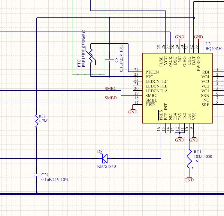
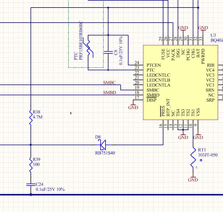
Our thought was put a capacitor on the present pin, which could hold the voltage level for a short period of time. But since the sampling pulse was only 4us and 10uA, the capacitor need to be very small to be charged up when not connected; and this will cause the time constant too small to achieve our target. So we tried to use the battery power as the pull-up, a 4.7Mohms resistor in serie to the PRES pin, and a 0.1uF capacitor from PRES pin to GND to hold the voltage. But when we do this, there is no voltage pulled up on the pin, no matter what resistor we use.

Do you guys have any experience on this? Any solutions to avoid the accidentally disconnection of the enable pin due to viberation?

Thank you very much.

Sincerely,

Chen

  • Hi Chen,

    The /PRES pin is pulled low and released when the test pulse is sent to check for system present every 1 second. It's very sensitive to capacitance due to the short duration of the pulse. It appears that the same issue you have with /PRES pin you will have with PACK+ and PACK- on the battery pack. How are you going to resolve that issue? How are you going to sustain power when PACK+ and PACK- are disconnected due to the vibration? Our recommendation will be to resolve the docking issue with the battery pack mechanically with proper locking mechanism and redundant contacts.

  • Hi Damian:

    Thank you very much for your reply. I totally understand your concerns. Just adding a capacitor definitely can't achieve what we want to do. With testing, here is our solution:

    This is a 4 cells battery. In this case, we don't use the internal pull-up pulse to detect the enable. A Schottky diode is placed on the /PRES pin, and this will avoid the current flowing from R38 to /PRES. When the battery is not enabled, the D8 negative side is pulled up by B+, and the /PRES will see high, and disable the battery. When the battery is enabled, which means the enable pin is pulled low to ground, and the D8 negative side is low to ground, and D8 positive side will see a voltage lower than 0.3V. Based on the spec, the max of VIL of the /PRES is 0.55V, so the /PRES will see as low and enable the battery. The current leakage is 2~3uA based on the values in the sch.

    Based on our test, this could enable/disable the battery as expected. We need do more test about the time constant. Do you think this is a valid solution for our use case?

    Thank you very much.

    Chen

  • Hi Chen,

    Looks like a simple innovative solution. The concerns I see is the VT of the schottky plus 0.1V max delta between GND and PACK- (across the sense resistor). Also I will recommend 100-1k resistor between D8 - to PACK- to limit the discharge current of C24 when PACK is connected to system/power tool.
  • Hi Damian:

    Thanks for your reply and suggestion.

    1. We will select the schottky diode carefully to make sure the voltage is under 0.55V, which is the max of VIL.

    2. Adding a resistor to limit the discharge current is a very great suggestion. I assume you mean adding a resistor between the capacitor C24 and the junction of R38 and D8? Because if we add a 100ohms resistor between D8- and PACK-, the voltage cross C24 will be very low.

    Thanks! 

    Chen

  • Hi Chen,

    The circuit look fine. I meant that R39 should go between C24, R38 and D8 node and connector to system/power tool that shorts the  pin to PACK-. What you did would work as well.

  • Hello Damian:

    OK I see what you mean now. Thank you very much for your reply!

    Have a good week!

    Sincerely,

    Chen