


Hi,
i'm testing an inverter with these features:
Fswitching=220KHz
Fout=3KHz-10Khz
Vout=150Vac
Pout=150W
Current feedback.
Sinusoidal output is obtained with transformer leakage inductor+output capacitor.
In the figure below there is the schematic.
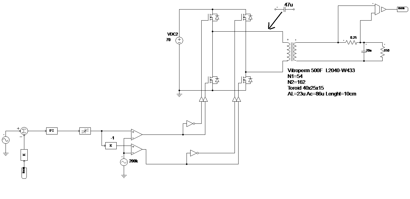
The problem is that a little DC component (about 100mA) put transformer into saturation and the output waveform has a distorsion as in figure

I don't understand from where it can come this DC component. Could you help me?
A capacitor could solve my problem? what features should have this capacitor? Ceramic or film cap? I had thought of 47uF@25volt as the voltage across it should never be too high.
Let me know.
