This thread has been locked.

If you have a related question, please click the "Ask a related question" button in the top right corner. The newly created question will be automatically linked to this question.

BQ24610: Charge current switched off before ITERM is reached; no CV phase

Part Number: BQ24610

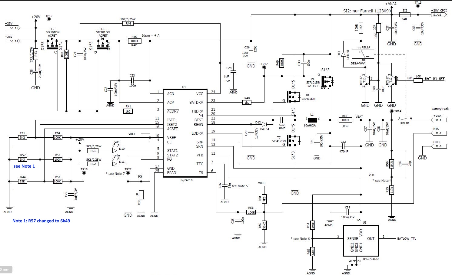
We are developing a circuit where we use the bq24610 to charge a 6S battery (25.2V fully charged). Our circuit is very similar to the application on page 26 of the data sheet.

We only modified the ISET1, ISET2, ACSET and VFB resistor dividers. We use the following resistors:

ISET1: VREF - 100k - MID - 8k2 - GND  Setting for 1,25 A fast charge

ISET2: VREF - 100k - MID - 3k3 - GND Setting for 0,1 A precharge and termination

ACSET: VREF - 100k - MID - 33k - GND Setting for IDPM = 4,1 A

VFB: VBAT - 1,21MOhm - VFB - 110k - AGND Setting for 25,2 V

Our Inductor L1 is 10 uH/2A, Input voltage is 28 V. Following you can see a charging current curve we have measured. Additionally we measured the voltage at the battery during the Charge.

To this curves we have the following questions:

1) Why is the charging current already switched off at a current value of approximately 700 mA? We expect this switch-off later on at the ITERM threshold of 0,1 A.

2) Why is the battery voltage continuously rising? We would expect that a part of the curve should have constant battery voltage (Fastcharge Voltage Regulation Phase) by decreasing current.

 Regards

Christian

  • Hi Christian,

    1. Please measure the voltage at ISET2
    2. How did you measure the voltage? in the PCB board? At 00:20:00 it looks constant voltage.

    Alen Chen
  • Hi Alen,

    many thanks for the quick answer.

    1) We measure at ISET2 a voltage of 0,202V.

    2) We measured the battery voltage with a data logging multimeter.

    Our chain is PCB <-> connector 1 <-> Adapter board  with banana plugs and a 1A glass fuse <-> connector 2 <-> battery pack.

    The point where we measure is at the banana plugs of the adapter board. Between our multimeter and the battery pack there is only the fuse, the connector 2 and wires with approx. 10 cm length.

    To give you all informations I have to mention that we have a closed relay contact (rated for 5 A) between the RSR-Shunt (SRN-side) and the connector 1. During our measurement this contact was permanently closed.

    Regards

    Christian

  • Hi Alen,

    sorry, but I have to tell you that we have measured the curves with a different ISET2 configuration as I have told you first.

    The configuration was:

    ISET2: VREF - 100k - MID - 6k49 - GND (Setting for 0,2 A precharge and termination)

    With this configuration we measured the 0,202 V at ISET2.

    Regards

    Christian Zellner
  • Hi Christian,

    The voltage on ISET2 Pin looks good. ISET2 Pin also set the precharge current. Can you measure the current of precharge.  you need set battery voltage lower than 3V/Cell. 2.3V is fine.

    Alen Chen

  • Hi Alen

    we could measure a precharge current of approximately 700 mA.

    We could send you our schematic if it helps. Please send me an e-mail address or tell me the way how I could attach it to a reply.

    regards

    Christian
  • Hi Alen

    here our schematics, hope this helps:

    Regards

    Christian

  • Hi Shrenidhi,

    How many PCBA with this problem? and you can please measure the battery voltage on TP14 as well.
    Please short REL1B and remove T9 than try again.

    Alen Chen
  • Hi Alen,

    at the moment we have unfortunately only one PCB for our tests. More PCB's we will get end of next week earliest.

    In the meantime we did the following measurements:

    Measurement 1: REL1B not shorted; battery pack connected, battery discharged to a voltage of approx. 18.4 V

    We measured the charging current after switching on of the 28V Input power supply with a multimeter:

    --> charge current starts with approx. 800 mA

    At the same time we measured the voltage at TP14 with an oscilloscope:

    We did the same measurement once more and measured the voltage at VFB:

    There we see a voltage peak at the time when the 28V input power supply has been connected.

    We suspect that this voltage peak could cause our problem, what do you think about? 

    After that we shortened REL1B and did the same measurement as before:

    With the shortened relay contact the chargig starts with approximately 200 mA as for the precharge expected.

    We replied this measurement three times, always 200 mA.

    Remark: We have not removed T9 because its an SMD part and we would like to avoid to remove it.

    Any more ideas what we could measure or do?

    Regards

    Christian

  • Christian,

    Why you connected T9 before Rsense(R47)?

    I think the voltage peak occur  because the long battery cable with high parasitic inductance.

    Please pull low BAT_ON_OFF to make sure the relay always on. Then try again.

    Alen Chen

  • Hi Alen,

    the connection of T9 to the connection between L1 and R47 is a mistake. It should indeed be connected to TP14. We have to change that in the next redesign. Do you think that this is the cause of our Problem, we don't think so?

    In the meantime we tried something. The colleague I am working with removed C34 and after that he told me that the bq24610 started the charge always with 200 mA precharge current. (With C34 populated we had always approx. 700 to 800 mA.)

    With the removed C34 my collague did a complete charge to check if the Iterm threshold is than at 200 mA too. Unfortunately Iterm threshold stays at 700 mA.  

    Sorry to say but after that measurement something happens and the bq24610 broke down. We don't know the reason why. My colleague tries to exchange the bq24610. So at the moment we have no working PCB. More PCB's we get beginning of next week earliest.

    If the exchange of the bq24610 should be successfull, we will continue searching the problem. What else could we try?

    regards

    Christian

  • Hi Christian,

    I agree with you I also don't think T9 can affect termination current. But to avoid the interfering, we still need to remove it.
    Try to remove T9, pull low BAT_ON_OFF then do again. You can check the voltage between SRN and SRP on C32.

    Alen Chen
  • Hi Alen,

    sorry for the delayed answer but in the meantime we have got three more assembled PCBs. We tested them and luckily two of the three boards work properly. We examined the 3rd one and after a re-heating of its bq24610 it works properly too. Unfortunately we couldn't find the cause of the problem with the very first PCB (where we discussed about) until now.

    At the moment we suspect that we have to much solder paste under the bq24610 because currently we have a square cut in the stencil which has nearly the same size as the thermal pad size. We will modify our stencil data accordingly to the stencil recommendation for the RGE package in the datasheet, means to divide it into four smaller squares. We will use this modified stencil for the next assembly.

    Could this be the cause of our problems, what do you think?

    Do you have anymore soldering or stencil recommendations additionally to the datasheet?

    Best regards

    Christian

  • Hi Christian,

    You can refer to the section land pattern data in the datasheet and you also can refer to IPC7525 for stencil design . We have many customers that using this package without any problem.
    Please consult with your soldering factory as well.

    Alen Chen