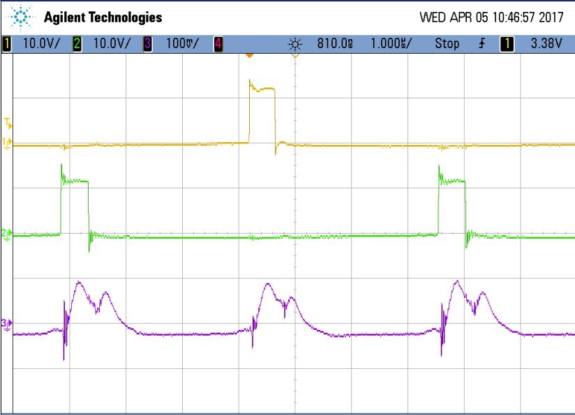
Using the UCC2806 in current mode, buck converter. The A and B outputs drive 2 separate MOSFETS alternating. The inductor is common to both MOSFETS. Frequency is set to 275 kHz at inductor, so 275/2 kHz per MOSFET. Current sensing is with transfomer, , peak current sensing.
I've been struggling to get this to work correctly and noticed that the error amplifier is having a lot of trouble at each rising edge of the A or B outputs. Instead of keeping the output voltage of the error amplifier constant, there are some very large excursions - droops - at each switching event. I am pretty sure this is causing the comparator to switch when it should not. Under typical understanding of a closed loop op-amp system, the V+ and V- should always be equal. In this case, the error amplifier is blowing it - can't seem to keep up. I've checked the non-inverting input, and it is solid at all times. Checking the inverting input, it moves drastically and in tandem with the output of the error amplifier (which seems to be doing the wrong thing).
The closed loop response is rather good...just not high enough bandwidth, but good enough to get rolling. The phase margin at 0-dB cross over is over 50 degrees, and the gain margin at 0 degrees phase shift is greater than around 15 dB (off top of my head). I don't think there is a loop stability problem.
Things get very out of hand when the load is increased. The A and B outputs get symmetrical, to the point where one is very small and the other is large (in duty cycle).
Any thoughts?


