This thread has been locked.

If you have a related question, please click the "Ask a related question" button in the top right corner. The newly created question will be automatically linked to this question.

BQ76940: capacitor on reference schematic

Part Number: BQ76940
Other Parts Discussed in Thread: BQ76200

Hello,

We're using the BQ76940 in our several BMS models with different characteristics. In last designs, we use also the BQ76200 as a gate driver for driving n-MOS on positive terminal of the battery pack.

By looking to several reference schematics, I can see there are always two pairs of capacitors:

  • in parallel to output terminals
  • bridging MOS

That's for both architectures, with and without the BQ76200. Here some examples:

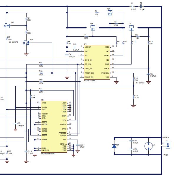
SLVA729A: C1-C2 and C17-C23 pairs 

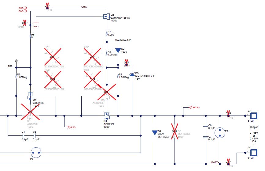
SLVU925B: C4-C5 and C6-C7 pairs

What is the purpose of such capacitor pairs?

We don't have them in my circuits, so we would like to better understand if we have to add them in our new designs.

Thank you and best regards

Matteo

  • Sorry, maybe schematic drawings are not been properly loaded in previous post. I add more references:

    SLVA729A, Fig.1 on page 4: C1-C2 and C17-C23 pairs

    SLVU925B, Fig.26 on page 44: C4-C5 and C6-C7 pairs

    Thank you again

    Matteo

  • The capacitor pairs are for ESD protection. They provide a low impedance path between the pack terminals and past the FETs. 2 capacitors are used in series so that they do not form a single point failure at assembly or in service. The 2 caps in the pair will commonly be oriented at right angles so they experience different mechanical stress. Search the web, check references, or refer to your capacitor supplier for capacitor failure information.