This thread has been locked.

If you have a related question, please click the "Ask a related question" button in the top right corner. The newly created question will be automatically linked to this question.

BQ24070: Charger and Battery Load

Part Number: BQ24070

We are using a BQ24070 charger/PMIC in the design of one of our products. Everything in our product is powered off the charger output (pins 15-17) except for one item which can present a heavy load (up to 100-200mA). This one item that can present a heavy load is powered off the battery directly, and not off the charger output.  

Is it good practice to power devices directly off the battery when the charger is trying to charge the battery? What are the implications of doing this? Can the BQ24070 get confused if it is charging the battery and one component is drawing energy out of the battery at the same time?

  • Hello,

    Yes, you could pull current from OUT pin at charging process. Normally, the 100-200 mA current is OK. You need to check other reasons for your issue.
  • I forgot to mention the current draw is not constant. It can vary quite a bit. Could large variations in current draw confuse the charger?

    Really, it is a cycling load that can vary between 50mA and 200mA every 40 seconds for about 10 seconds. So on for 10 and more or less off for 30. This current draw can sometimes make the apparent battery voltage sag down to to 4.06V, which is below the recharge threshold. Can this cause issues?

    I'm really not concerned about the current draw, but I'm more concerned about what the current is doing to the apparent battery voltage presented to the charger. 

  • Hello,

    Does your current issue happen at OUT pin, or BAT pin, can you make it clear? And if it is OUT pin, could you tell me where is the current from, VIN or BAT?
    For analysis, recommend that capture the waveform when VBAT decrease, includes IIN, IOUT, VBAT, CHG.
  • Hi Kerry - 

    Sorry I wasn't more clear. The issue is happening at VBAT. The load that varies is connected to VBAT, in parallel with the battery, not on the OUT pin. 

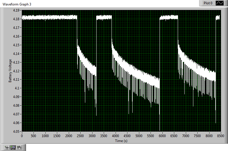
    Right now, I can provide you with a screenshot of what the VBAT line does with this load in parallel with the battery. What this graph shows is the device is in fast charge (constant voltage) to start. When the voltage drops down to 4.15V the charger is charge done. Then, a short time later, the charger kicks back into fast chart (constant voltage) because of the load on VBAT. As you can see, there are a lot of transients on the VBAT line that drop below 4.1V, the recharge threshold, and we are wondering if this is confusing the charger. When we swap the load in question to the OUT pins (15-17), we don't see the behavior. Instead, we see a smooth battery decay. 

    To get you the waveforms you requested, let me ask a few questions to make sure I will provide you with the correct graph. The questions are:

    1. Is IIN the input current into the IN pin (pin 4)?

    2. Is IOUT the current out of pins 15, 16, and 17?

    3. Is CHG the charge current out of pins 5 and 6?

    Once you confirm that I will set that up and get all of those waveforms on one graph. 

    Here is the graph of VBAT by itself with the load on VBAT:

  • Hello,

    Recommend that connect your load to OUT pin, rather than BAT pin, this is the normal usage.

    When you discharge your battery, let it below the VRCH(discharge threshold), IC will start recharge, this is normal.
  • I'm confused...

    What made you change your mind that this isn't normal useage? Is it the fact that the current demands are dynamic or is it simply just not normal useage?

    Thanks
  • Hello,

    I mean that " connect your load to OUT pin, rather than BAT pin" is right connection.
    And When you discharge your battery, let it below the VRCH(discharge threshold), then IC will start recharge