This thread has been locked.

If you have a related question, please click the "Ask a related question" button in the top right corner. The newly created question will be automatically linked to this question.

TPS54202: 1kHz Ripple: Can the phase boost capacitance be used to suppress it?

Part Number: TPS54202

Dear TI Team,

I had posted in one of the other threads regarding this. But since that one has been marked as answered, I'm opening a new one.

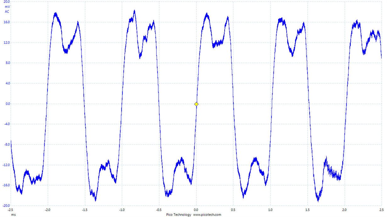
In my application, there is a ripple of about 1kHz in the TPS54202 Output. The amplitude is about 40mV p-p

I tried adding a phase boost capacitance (in parallel with the top feedback resistance). The ripple goes down as capacitance increases.

At about 10nF, the ripple is almost gone. Is this OK? The datasheet recommends adding only a few pF. 

Will the loop stability be compromised in any way as the components age? 

Circuit Parameters:
Vin - 18V
Vout - 12V
L - 47uH
C - 47uF - Aluminium Polymer
Cap ESR - 25mOhm @ 100kHz.

Tested Load: 1.5A

Measured Ripple Voltage(p-p): About 40 mV without phase boost cap. 

Thanks in advance,

Vikram

  • Hi,
    The 1kHz ripple is caused by spread spectrum function, the frequency recirculate from -6% to +6% of the 500kHz, the recirculation period takes 512 siwtching cycles, so it introduces in 500kHz/512=0.98kHz noise.
    The 10nF cap is a bit too large, it may affect the loop stability, especially at cold temperature, need to verify if the regulator is stable or not.
    You can try small inductor, say 22uH, small Cout, say 22uF cap with small ESR. If that still can meet requirement, continue to add 47pF~100pF phase boost cap (use the recommended feedback resister divider).
    BTW, What's the targe ripple ctm required?
  • Dear Mr.Luke,

    Thanks a lot for your answer.

    I'll try with an 22uF MLCC and get back to you.
  • Dear Mr.Luke,

    I replaced the existing 47 uF with multiple 10uF MLCCs.

    Although the MLCCs are rated at 10uF, the capacitance falls to about 4uF at 12Vdc. So I tested with 3/4 caps in parallel.

    Even now, the ripple voltage remains the same at 38 mVpp for load currents from 0.5A to 1.5A.

    I also added the phase boost capacitance of 100pF. But there is no effect.

    Should I reduce the Inductance? Most of the time, the circuit will operate at light load only (<0.7A). So, I had chosen the 47uH value from your datasheet formulas. Moreover, we had already procured a lot of 47uH Inductors for this project. So, changing it is a bit difficult.

    The ripple voltage is not extremely critical in our application. But, lesser the better.

    Kindly give your feedback on this.

    Also, please tell me what is the effect of the phase boost capacitance? Will it reduce the Switching frequency Ripple or the 1KHz Ripple ?


    Thanks,

    Vikram.
  • Hi Vikram,
    If the ripple is not critical, suggest not to add too large phase boost capacitance, it's better to follow the datasheet. The phase boost cap will increase the bandwith of the converter, when the bandwith is mucher higher than 1kHz, then the 1kHz ripple can be suppressed well. However, the larger phase cap will make the converter more sensitive to noise, which will cause stability risk.
  • Dear Mr.Luke,

    Thanks again for your response.

    We have decided to go forth with the existing design with the 1kHz ripple.

    Out of curiosity, what is the proper way to eliminate the 1kHz ripple, without adding too much phase boost capacitance?

    One of our future projects require a ripple voltage <15mVpp.

    What needs to be done to get the perfect output voltage as given in your datasheet?

    It will be really helpful if you could give me some pointers.


    Thanks,

    Vikram.
  • Hi Vikram,
    Just as I mentioned before. The 1kHz noise can't not suppressed completely. So if your application is critical with ripple. Suggest use TPS54202H, it has amostly same spec as TPS54202 and don't employ spread spectrum function, which mean no additional 1kHz ripple.
  • Dear Mr.Luke,

    Thanks a lot for your time and patience.