This thread has been locked.

If you have a related question, please click the "Ask a related question" button in the top right corner. The newly created question will be automatically linked to this question.

Question about isolated DC-DC converter design

Hi,

In general, isolated DC-DC converter is either flyback converter or forward converter.

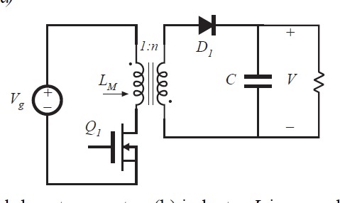
flyback


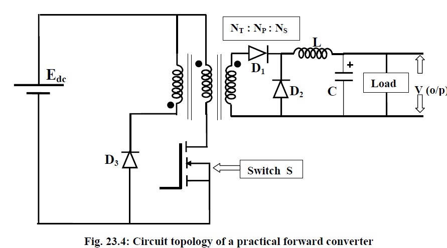
forward

But why not just have switching, then 4-diodes rectifier bridge? Is there anything bad about such design?

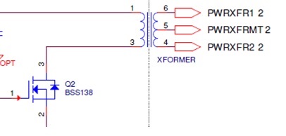
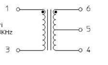
The “dots” of the transformer are as below

Hope to hear from you soon

Thanks and best regards,

KH

  • Hello KH,

    The two main switching topologies that you mentioned, flyback and forward, as well as almost all of the others, involve duty-cycle control and filtering (averaging) to achieve regulation of the output voltage.

    An overly-simplified design using only a bridge-rectified transformer has a number of short-comings that make it impractical at best, and damaging at worst, to implement. The first is that there is no voltage regulation possible. When Q2 is on, Vin is applied across the primary winding and the output voltage is equal to Vin/N. If Vin is always fixed, then N can be chosen to deliver exactly Vin/N to the output while Q2 is on. But if Vin varies, Vout will also vary as Vin/N no matter how much the duty cycle of Q2 changes. When Q2 is off, there is no defined voltage across the primary winding, so Vout (during Q2 off time) is also undefined. In an ideal situation, the winding voltage is zero, so Vout would also be zero. The requirement for regulated Vout is that Vin is fixed and duty cycle = 100%. The case for an overly-simplified flyback is even more unrealistic. 100% duty cycle is impossible because energy is only delivered to the output during Q2 off-time. This energy can be regulated with duty cycle but the output voltage is not constant. Vout goes to zero during the Q2 on-time. Without regulation, excess Vout may damage the load, and without current limiting, excess peak currents may damage the switching components.

    The main point is that switched-mode regulation relies on state-space averaging to accomplish output voltage regulation, and the averaging is done by output filtering. In a forward-mode topology, an L-C filter is used where the output inductor L limits the amount of current that can be transferred through the transformer during the Q2 on time. In a flyback topology, an output capacitance is sufficient, because the transformer primary inductance limits the peak current during the on time. Now, in either case, the Q2 duty cycle can be modulated by a controller to be able to regulate the average output voltage to the load even as input voltage and output load levels vary. And the “size” of the output filter determines the amount of residual ripple voltage superimposed on the regulated average output voltage.

    There are special cases where simplified switching and rectification of the transformer can be used, such as in certain point-of load distribution schemes, but these are indeed special cases. In these cases, all of the regulation and filtering has already been accomplished by another part of the overall power conversion architecture, and high-frequency transformer switching (at ~100% duty cycle and without filtering) is done locally to allow a pre-regulated pre-filtered high voltage to be distributed at low loss, and transformed to low voltage at the load, for small size.

    I hope this answers your question.

    Regards,
    Ulrich
  • Hi Ulrich,

    Can i check with you on some circuit design and hope that you can share me some thoughts,

    This is a real product (4-20mA) that is already being sold in the market. I left out many parts of the circuit as I can’t reveal too much.

    1.       Vin is fixed. There is voltage regulation circuit before feeding voltage to primary winding.

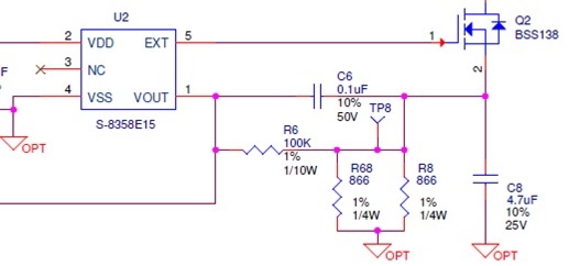
    2.       There is a controller, U2.

    3. Here comes the unconventional part, in stead of Vout feedback via optocoupler/transformer, they used a fixed primary side design. This is ok as long as you know your load does not vary.

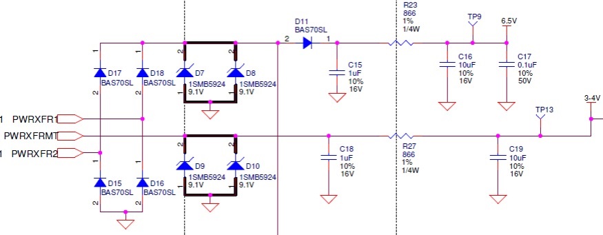
    4. Output filtering has only RC, no L, unlike forward topology. This may look strange to you à  866 ohms looks like it will waste a lot of power. But in our industry, this is common, product used in oil & gas industry. Our current is very low. The design do have explosion proof --- intrinsic safety. R23, D7 to D10 are there for intrinsic safety. 

    What I’m trying to do is to understand what they voltage waveform would be like.

    Am I right to say the following?

    The wave form of primary is DC while on secondary side, it is AC. The turns ratio is 1:1.

    Hope to hear from you soon!

    Thanks and best regards,

    KH

  • Hello KH,

    Your 6.5V secondary is configured as a;
    1. full wave bridge rectifier
    2. zener clamp
    3. another rectifier
    4. RC filter, current limited output 866 ohm

    I can not tell what would be driving the 3.4V output at PWRXFRMT

    If you can send a better picture of the transformer connections it would help.

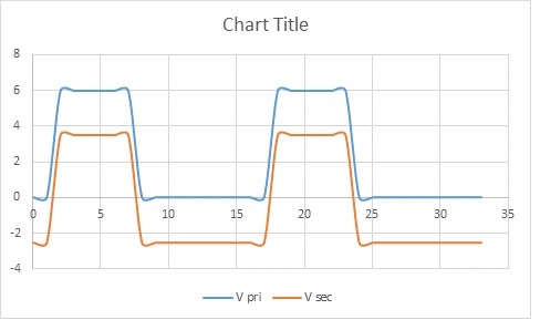
    For the 6.5V I have drawn what I expect the voltages to look like.
    After the full wave bridge you should see small dips corresponding to the AC input transitions at the bridge input.

    Then it gets further filtered out to the output.

    Here is a picture of what I expect the 6.5V signals to look like.

  • Dear Ed,

    Thanks for the explanation, for

    2. zener clamp
    This is used as a TVS, it is normally not active. i.e. the voltage there is below 9V.

    Am I right to say full wave rectifier bridge is unnecessary? Because unlike mains 60 hz, this is not true AC. The current will only flow in one direction (see attached).
    There is no negative cycle. Is this right?

    By the way, the primary should be on the left, secondary on the right. I drew wrongly, but you get the picture.

    Hope to hear from you soon!

    Thanks and best regards,
    KH
  • Without seeing the entire circuit I can not comment on whether the bridge is needed.
    However this seems to be some kind of center-tapped transformer, there will be AC present.
    AC is the only way a transformer can work.

    I still think the bridge is needed at this point.
  • Hi Ed,

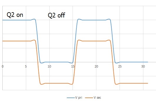
    Am I right to say the following?

    If Voltage in primary has only 0V and +6V, the voltage on secondary will have the DC component removed, like in picture below.

    In other words, the secondary voltage has an average of 0.

    Thanks and best regards,

    KH

  • Hello KH, both primary and secondary must both have an average voltage of 0V.

    Transformers work from a Volt x Seconds applied basis.
    T1: Primary will apply Vpri for Tsec (VxS), building up flux in the core.
    T2: The transformer core must reset itself, so after T1 the primary voltage will reverse and bring the flux back to where it started.

    If the transformer has a DC component then eventually the core will saturate.

    This picture illustrates the voltage action on a transformer.
    Looking at the primary voltage, V+ is applied for +VxS and then the flux forces the exact same reverse voltage -VxS
    The net result on the primary is 0V average.
    There is deadtime after the core resets until the next cycle.

    The secondary will look exactly the same, except the voltages are scaled by the turns ratio.
    Vpri/Vsec = Npri/Nsec where N is the turns ratio.

    5VWINDING264.TIF