This thread has been locked.

If you have a related question, please click the "Ask a related question" button in the top right corner. The newly created question will be automatically linked to this question.

LM3409HVEVAL: External Dimming with 2 Diodes

Part Number: LM3409HVEVAL
Other Parts Discussed in Thread: LM3409HV, LM3409, TPS92515, TPS92515HV

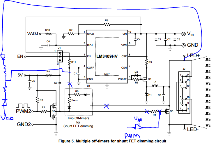
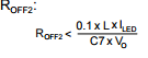
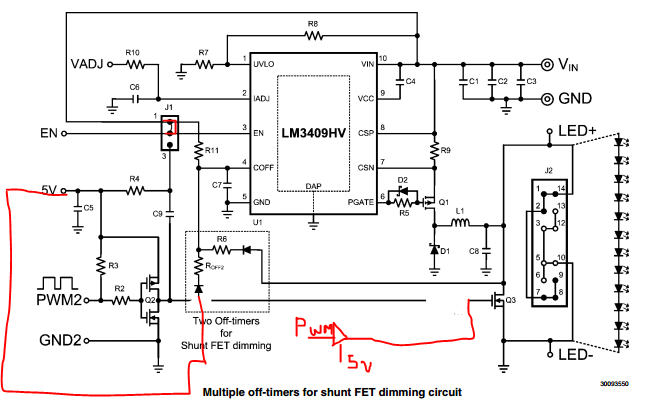
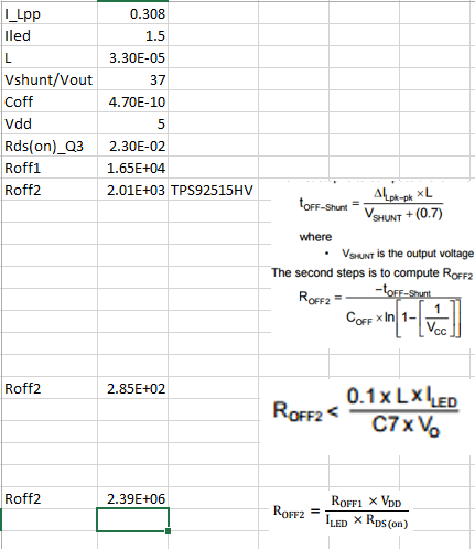
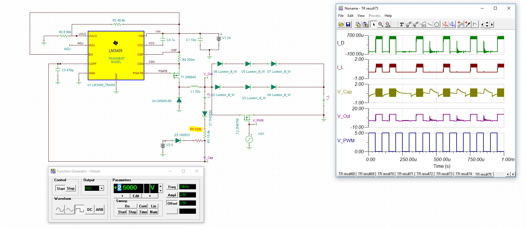
In this modification, I replace the R6 to increase the switching frequency. I do not want use the EN pin to do the shunt pwm dimming. Hence, I make a little modification by adding 2 external diode to preventing the coff being completely discharged. However, when I feed in the external pwm signal to drive the Q3, the switching is messed up. It did not switch properly (sometimes 30% on, 50% on, 20%on). I also notice that the formula to calculate the Roff2 is different between the and 

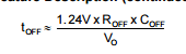
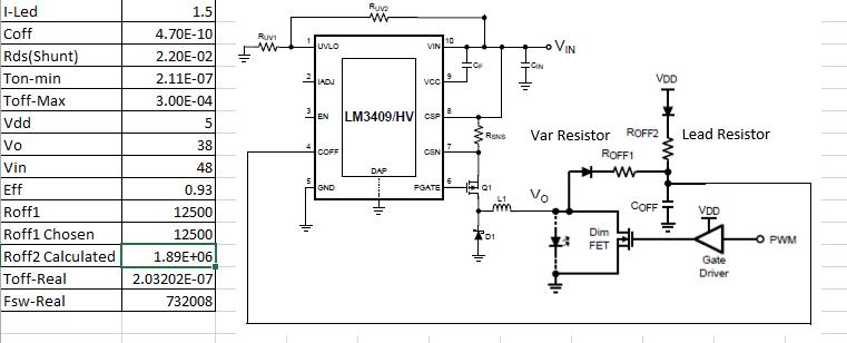
For this case, I am using the LM3409HV datasheet's formula.

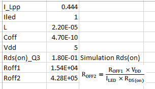
Also, I have doubt regarding the Rds(on) value that I should plug in into formula. In this case, I am choosing the Q3 Rds(on) value which is 19mOhm.

The Roff2 from LM3409HV vs LM3409HVevm is differ so much.

In my opinion, the Roff2 should be calculated with the same formula off Roff1, but changed the Vo to Vdd (8.3.2.2 Controlled Off-Time equation: 6). So the Roff2: ~13200ohms.

Thanks,

  • Hello,

    You are right about the equations. The EVM was developed before some OFF timer issues were well understood from what I can gather. But yes, the Q3 Rds(on) is what you should use. The point is to try and make the inductor peak-to-peak current ripple the same when the shunt FET is on as it is when the shunt FET is off. That way you will get consistent dimming waveforms. That of course is assuming that the normal switching frequency is much greater than the shunt FET dimming frequency.

    Regards,

    Clint

  •   in the end I should use the above formula to calculate the Roff2 value. I am little lost in this equation because it does not count the Vdd. In addition, the Roff2 is 0.1*33E-6*1.5/(470E-12*38) = 277ohms which is very low. If I try to use   solving the Roff for the Roff2, and use the toff calculated from the known Roff1 and Coff and Vo (replaced to Vdd). I get a very different result which is around 13.7kOhms.

    I was thinking that I should maintain the switching frequency the same when the Fet is shorted. But it turns out that I am wrong.

    So, my question is that the Roff2 formula is given by the LM3409HV datasheet is wrong and LM3409HVEVM is the most correct one?

    For my application, I want to do the external pwm with varying frequency (1kHz-100kHz).

    Thanks,

  • Hello,

    The datasheet equation is an approximation and in that first equation you would use Vdd rather than the output voltage to do the calculation. Usually in the end the value will need to be tweaked some to make the inductor current ripple the same when the shunt FET is on. So I would go ahead and use the EVM equation with the understanding that for the best shunt FET dimming performance it will need some adjustment. For an example of what I mean look at the shunt FET dimming section of the TPS92515. The two devices operate in the same manner with the only real difference being that the 515 has a 1V COFF threshold rather than the 1.24V threshold in the LM3409.

    Regards,

    Clint

  • Thanks for your response. I have been damaging the evaluation board because I was curious why the PWM switching is not consistent.
    After I got a new replacement board, I will go ahead and used the equation from TPS92515 with varying the delta inductor current ripple.
  • Sounds good. Just one side note, I don't know what changes if any you have made to the EVM, but do not try and shunt FET dim with an output capacitor or you will cause damage. That kind of cap charge/discharge current can easily cause you to go beyond the SOA of the shunt and switching FETs.

    Regards,

    Clint

  • Hi Clinton,

    Unfortunately, I am damaging another board on Friday.

    Those redline are the modification that I made. I remove the R1 so that I could use my own pwm driver. Also, I set the J1 into mode 1 which EN pins is shorted to Vin.

    Here is the specification:

    Roff2 = 2kOhms

    PWM Driver = TI UCC27325D

    Diode = SB160 (Schottky Diodes Vr = 60V and If = 1A).

    The damaged part that I know are:

    Q3 and Q1, but I am also assuming that the chip also damaged.

    My hypothesis:

    1) When the Q3 on, then LED is shorted, then when 5V is charging the Coff it caused it overvoltage since the maximum is around 4V. Hence damage the board.

    2) The PWM driver that I used is causing problem (less likely the case) because before I am trying to modify the circuit I used mode 3 external pwm dimming with J1 shorted between pin 2 and 3. Also, I feed the pwm signal on PWM2 pin.

    The reason that I want to use the extra 2 diodes is: I will use this chip and the shunt pwm signal with a vary frequency. Problem with EN pins is it will cause a problem when my off times is violates the max of times from the LM3409HV.

    Here is the board with missing Q3,

    Regards,

    Yo Shua

  • Hello,

    It's hard to be sure without any waveforms, but it is unlikely that you are damaging the COFF pin since it limits itself to 1.24V. But here are two thoughts:

    1. I am not sure exactly what your load looks like or what kind of lead lengths you have between the shunt FET and the LEDs. But shunt FET dimming edges are very fast so if you have parasitic inductance between the FET and the LEDs you can generate excessive voltage spikes in both directions which could damage the shunt FET. Ideally the FET is directly across the LEDs but if it can't be you can prevent damage to the FET by putting an RC snubber across it. I would look at the shunt FET waveforms to see if you might need a snubber.

    2. 2kohm seems like a pretty low value. That will result in a relatively short OFF time and the device will need to compensate by making the ON time very short (you need a very low effective duty cycle with the output shorted). You could be running into two possible things here. If the ON time wants to be lower than the minimum ON time then the current could run away. The other thing is that you might be trying to switch at way too fast of a switching frequency with the shunt FET on and that could cause VCC to collapse and you could damage the switching FET.

    In any case is EN dimming fast enough for you other than the low power shutdown mode delays you can get? If so you can use the UVLO pin for PWM dimming. It behaves the same as EN except that VCC will remain alive so it does not go into shutdown and will respond very quickly regardless of how long the off time is.

    Regards,

    Clint

  •  2402.calc.xlsxHi,

    Thanks for the answer.

    1. I did not replace the shunt fet (Q3), I only drive it with external pwm driver to control the Q3.

    2. I got this calculation based on TPS92515HV formula. The idea of this things is to maintain the ripple current. I have 3 different calculation from 3 different formula.

    I do not really understand why the the chip is malfunctioning because I dont see any direct path between Q3 and the chip other than Coff pins. I removed the Q3 and test in under normal operation, it only lit once and dead. 

    On the first, I used TPS92515HV. Second, I used LM3409HV evaluation module formula, and on Third, I used the LM3409HV data sheet formula.

    I understand that by using UVLO for PWM dimming will not cause the off time maximum, but in this case I want to extend our existing light controller, and we have used PWM dimming to completely shutoff the LED with very fast response because our application is really high sensitive.

    Another fact, I have already damaged 3 Evaluation Board by this experiment. It went well with EN + Shunt PWM, but when I want to dim it to lower frequency its behavior is not correct.

    another fact, when I drive the Q3 directly with 50% PWM signal 7-15kHz, it does not behave correctly. The Vout squarewaves is not 50%, it varies from 20-50%.

    Do you have any clue of how can I implement it correctly?

    Regards,

    Yo Shua

  • Hello,

    Ok, I have now confirmed with the original systems engineer for the device regarding the equation. The latest datasheet equation is the correct one for the LM3409 and Roff2 is usually a much higher value than Roff1. 2kohm will be too short of an off time and the current will keep ratcheting up until the inductor saturates and it will blow the FETs up. Have you tried the higher value you have calculated?

    Thanks,

    Clint

  • By the way the shunt FET dimming method on that board has known issues. You can hit maximum OFF time scenarios that will mess up the duty cycle which is what you are probably seeing. This is why the 2 diode circuit was later added to the datasheet because shunt FET dimming issues were much better understood after that EVM released. So the correct way of doing it is to connect EN to VIN and use the diode circuit with Roff1 and Roff2 like you are doing. You just need to have the correct Roff2 value.

    Regards,

    Clint

  • I tried the Roff2 value with the last formula and it did not work. Hence, I tried it and followed your suggestion on earlier discussion, to use TPS92515HV.

    I have done a simulation to prove that by using the last formula will not work, but if I lower the resistance by a magnitude, it seems work.

    Now I am really hesitating to try this again, I only have 1 left EVM available (bought 4 and broke 3). I just need a definite proof that this chip works as intended. And now, I need only to figure out the correct Roff2 (not guessing).

    What I understand is, the Roff2 is really high that set the off time longer than its maximum.

    I hope you could help me to get through. Thanks for you fast response.

    Best Regards,

    Yo Shua

  • Hello Yo,

    The equation is not always exact due to tolerances in all components and simulations generally don't take a lot of that into account. But it does work as expected with some tuning. This is why I mentioned using a current probe to monitor the LED current. You start with a higher value which is what the equation generally gives (higher values aren't dangerous where lower values can be) you and watch the current ripple each cycle. You may need to reduce it to match the peak to peak inductor/LED current depending on the diode Vf and the actual FET Rds(on). There are many good designs done with this device so it can be done. But a value that is too low will damage the FETs.

    If you would like you can let me know your input voltage range, LED stack voltage, and LED current and I can maybe give some better input with the full information. But you are correct in the assumption that under certain operating conditions what you calculate may be beyond the LM3409 maximum on time, but that is usually only at low PWM frequencies, not in the kHz+ range though usually.

    Regards,

    Clint

  • Thanks for you help. I just really want to get this EVM board work.
    The input voltage will be 48V +/- 5%.
    Led Stack Voltage will be around 37-39Volts
    Led Current 1.5A

    I was really curious why in the simulation of LM3409 does not really work if I put a high resistance. Considering my PWM frequency is 10kHz, but I think you have answered those question.
    I am really thankful for your help, since this is my very first work at our company and I was assign to develop the new led controller.

    Regards,
    Yo
  • Hello Yo,

    I'm not sure why it looks so bad with the higher resistance, but most transient models have some issues, especially when you have corner cases. With that output voltage I can see why the Roff values are so different. I'm not sure exactly how concerned you are about efficiency, but you can tune the behavior further if you are willing to burn some power. A high Rds(on) FET would help speed up the inductor ramp rate so lower Roff2 values can be used. You could even add some resistance in series with the shunt FET.

    In any case you should be able to tune it well enough with some bench work.

    Regards,

    Clint